Resource allocation in a digital communication network

Active Publication Date: 2017-04-27
BRITISH TELECOMM PLC
View PDF3 Cites 7 Cited by
  • Summary
  • Abstract
  • Description
  • Claims
  • Application Information

AI Technical Summary

Benefits of technology

[0039]In particular where a high frequency bandwidth technology is deployed from nodes closer to the customer than an existing lower (but overlapping) frequency technology that is deployed from nodes further away from the customer, preferred embodiments of the invention use noise measurements or measurements of other characteristics made at the second (i.e. closer) deployment point (or other methods) in order to determine what frequencies are actually in use for the “longer” technology, then use those measurements to configure the frequencies to be used for the “shorter” technology (generally by setting a minimum frequency) such as lo avoid crosstalk interference between the respective longer and shorter lines. This ma

Problems solved by technology

It is well-known that transmissions on one subscriber line may cause interference on another subscriber line.
However, subscriber lines between higher-tier DSLAMs and their customers' DSL modems tend to be significantly longer than subscriber lines for lower-tier DSLAMs, such that a signal on the longer subscriber line is significantly attenuated by the point at which it is bundled together with the subscriber lines for lower-tier DSLAMs.
Thus, full power transmissions by lower-tier DSLAMs can often be the cause of high levels of crosstalk on higher-tier subscriber lines using the same frequencies.
This generally decreases the chance of crosstalk on the DSL connections between the exchange and the customer.
A problem with the ANFP identified by the present inventors is that while the ANFP generally reduces the chance of crosstalk on higher-tier DSL connections, it generally also reduces the capacity of lower-tier DSLAMs when there is overlap in the frequencies used both by lower and higher tier DSLAMs.
As DSLAMs are located closer to customers, the ANFP technique will become increasingly more inefficient in terms of the total capacity of the network.
This is generally a manual and time-co

Method used


Image

  • Resource allocation in a digital communication network
  • Resource allocation in a digital communication network
  • Resource allocation in a digital communication network

Examples


Embodiment Construction

[0045]With reference to the accompanying figures, methods and apparatus for performing a resource allocation process according to a preferred embodiment will be described.

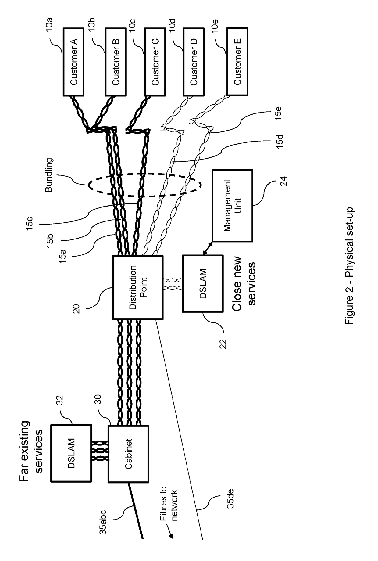
[0046]Briefly, FIG. 2 shows a physical network set-up in which customers (generally, 10) receive communications services via respective copper-pair lines 15. These services are provided via two different nodes, which in this example are shown as a distribution point 20 (located relatively near to the customers 10) and a street cabinet 30 (located further away from the customers 10). These nodes are in communication (via respective fibre connections 35) with the Core Network via an Exchange (not shown).

[0047]Of the five customers shown, two customers, shown as Customer D (10d) and Customer E (10e), are shown as receiving their communications services via a new, close (i.e. short-range), high-frequency (and generally faster) service such as G.fast, while three other customers, Customer A (10a), Customer B (10b) and C...


PUM


Abstract

Methods and apparatus are disclosed for allocating resources in a Digital Subscriber Line network, the network comprising at least one lower-tier digital subscriber line carrying signals according to a first protocol between a transceiver device at a lower-tier network node and a subscriber transceiver device and further comprising at least one higher-tier digital subscriber line carrying signals according to a second protocol between a transceiver device at a higher-tier network node and a subscriber transceiver device, the first protocol permitting signals to be carried at frequencies in a range having a higher upper limit than the second protocol.

Description

TECHNICAL FIELD[0001]The present invention relates to resource allocation in a digital communication network, in particular a Digital Subscriber Line (DSL) network.BACKGROUND TO THE INVENTION AND PRIOR ART[0002]A Digital Subscriber Line (DSL) connection is a connection that allows for the provision of digital communication over existing twisted copper pair subscriber lines. The term DSL is a collective term to cover a number of variations on the DSL technology, including ADSL (“Asymmetric” DSL), SDSL (“Symmetric” DSL), ADSL2+(a technique that extends the capability of basic ADSL by doubling the number of downstream channels), VDSL (Very-high-bit-rate DSL), VDSL2 (an improved version of VDSL), and others, including, in particular, “G.fast”, which will be discussed later.[0003]In general, a DSL connection comprises a copper subscriber line extending between two DSL modems. A first DSL modem is typically located at the customer's premises, and the second modem may be located at the loc...

Claims


Application Information

Patent Timeline
IPC IPC(8): H04M11/06H04L5/14H04B3/32
CPCH04M11/062H04L5/14H04B3/32
Inventor LINNEY, TREVOR PHORSLEY, IAN E
Owner BRITISH TELECOMM PLC
Why Eureka
Try Eureka