Electro-luminescence display apparatus

a display apparatus and electroluminescence technology, applied in the direction of instruments, semiconductor devices, organic semiconductor devices, etc., can solve the problems of increasing the degree of unevenness in the brightness of the electro-luminescence display apparatus, reducing the performance of the common line, and affecting the uniformity of the cathode voltage. , to achieve the effect of reducing the differences of electrical resistance of the common and improving the uniformity of the cathode voltag

Active Publication Date: 2017-05-04
LG DISPLAY CO LTD
View PDF1 Cites 96 Cited by
  • Summary
  • Abstract
  • Description
  • Claims
  • Application Information

AI Technical Summary

Benefits of technology

[0010]The inventor of the present disclosure has conducted research and development on an electro-luminescence display apparatus (e.g., self-emissive display apparatus such as organic light emitting display apparatus and / or quantum-dot light emitting display apparatus), comprising a cathode line (i.e., an auxiliary common line) to improve uniformity of a cathode voltage according to positions of the pixels within the pixel area AA of the electro-luminescence display apparatus, which is capable of reducing differences of electrical resistance of the common electrode according to the position of the active area AA. However, if an auxiliary common line is implemented, this may cause the following exemplary problems that need to be solved.

Problems solved by technology

Thus, a non-uniform brightness problem may arise if the distance from the cathode voltage supply unit, which can supply a cathode voltage ELVSS to the common electrode, increases.
However, if an auxiliary common line is implemented, this may cause the following exemplary problems that need to be solved.
Firstly, if the width and the thickness of the common line are reduced, the line resistance increases, thereby decreasing the performance of the common line.
On the other hand, if the width and the thickness of the common line are increased, the area for circuit elements (for example, a storage capacitor, a switching element and a driving element) that operate the sub-pixel may be reduced, and this may cause further problems.
For example, if the line resistance of the common line increases, the uniformity of the cathode voltage of the electro-luminescence display apparatus is degraded, thereby increasing the degree of unevenness in terms of the brightness of the electro-luminescence display apparatus.
Furthermore, if the line resistance of the common line increases, the degree of heat generated at the common line also increases, thereby increasing thermal stress, which is undesirable.
Accordingly, the capacitance of the storage capacitor may decrease and a voltage level supplied to the sub-pixel of the electro-luminescence display apparatus may increase, thereby increasing power consumption and temperature, or decreasing the brightness of the electro-luminescence display apparatus because of insufficient charging of an image signal at the sub-pixel.
Accordingly, if the above-described problems are present it may be difficult to increase the degree of integration of the sub-pixel, thereby making it difficult to realize an electro-luminescence display apparatus having a high degree of integration and high resolution.
For example, an approximately 55 inch display apparatus may have a problem with realizing a resolution higher than 80 pixels per inches (ppi), such as in a 4K ultra high definition display apparatus.
However, there are manufacturing limits and / or difficulties associated with interconnecting the common line and the common electrode, because the electro-luminescence layer such as the organic emission layer can be easily damaged by oxygen, moisture, hydrogen, etchant or high temperature.
Thus, it may be difficult to realize a high resolution electro-luminescence display apparatus depending on the configuration of the contact unit.
In such case, due to the limitations of the manufacturing process (e.g., photolithography process or etching process), there may be a variation in the thickness and width of each line.
However, in such a case, the manufacturing process becomes more complicated and the manufacturing cost may also increase.
On the other hand, if the common line is formed without the additional metal layer, the difficult in designing the high resolution electro-luminescence display apparatus may increase because of the area of the common line.
Particularly, it may be difficult to optimize the layout of various lines to increase the resolution of the high resolution electro-luminescence display apparatus.
However, in such a case, the width of the bezel of the electro-luminescence display apparatus may increase.

Method used


Image

  • Electro-luminescence display apparatus
  • Electro-luminescence display apparatus
  • Electro-luminescence display apparatus

Examples


Embodiment Construction

[0053]Advantages and features of the present disclosure and methods for accomplishing the same will be more clearly understood from exemplary embodiments described below with reference to the accompanying drawings. However, the present disclosure is not limited to the following exemplary embodiments but may be implemented in various different forms. The exemplary embodiments are provided only to complete the present disclosure and to fully provide a person having ordinary skill in the art to which the present disclosure pertains with the category of the invention, and the present invention will be defined by the appended claims.

[0054]The shapes, sizes, ratios, angles, numbers and the like illustrated in the accompanying drawings for describing the exemplary embodiments of the present disclosure are merely examples and the present disclosure is not limited thereto. Like reference numerals generally denote like elements throughout the present specification. Further, in the following d...


PUM


Abstract

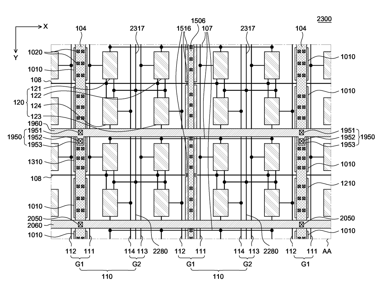
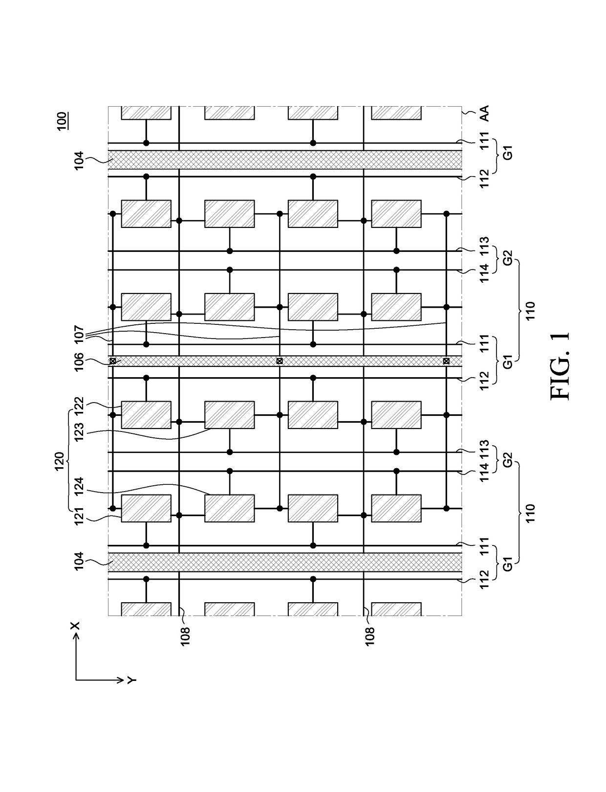
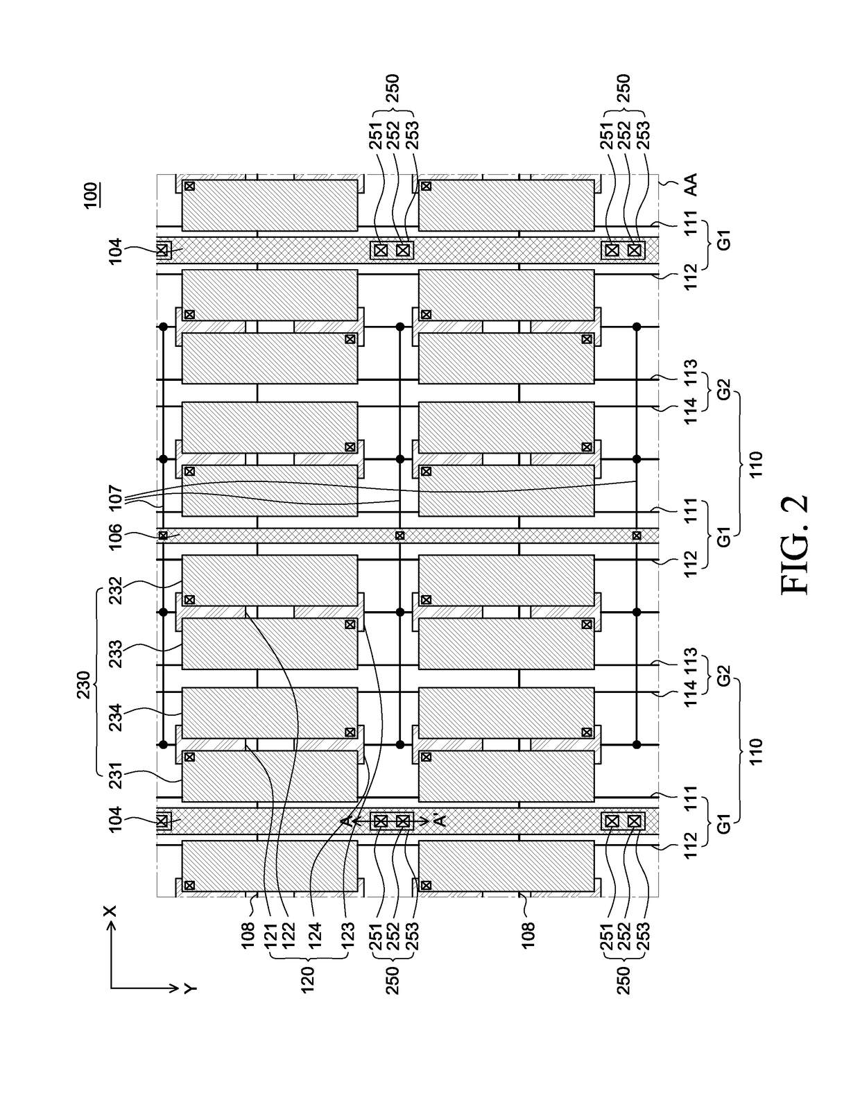
Described herein is an electroluminescence display apparatus comprising: at least one quad-type pixel circuit unit comprising a plurality of sub-pixel circuit units; at least one gate line disposed between the plurality of sub-pixel circuit units and extending along a first direction; at least one first data line group comprising a first pair of data lines disposed at both sides of the at least one pixel circuit unit and extending along a second direction; at least one second data line group comprising a second pair of data lines disposed between the sub-pixel circuit units and extending along the second direction; and at least one common line and at least one anode line disposed between the first pair of data lines of the first data line group and disposed along the first direction, the at least one gate line crosses with the at least one first data line group and the at least one second data line group.

Description

CROSS REFERENCE TO RELATED APPLICATIONS[0001]This application claims the benefit of Korean Patent Application No. 10-2015-0151829 filed on Oct. 30, 2015, which is hereby incorporated by reference as if fully set forth herein.BACKGROUND[0002]Technical Field[0003]The present disclosure relates to a top-emission type electro-luminescence display apparatus capable of improving uniformity of brightness of the electro-luminescence display apparatus by reducing a degree of deviation of electric potential between anode and cathode according to the location of the respective pixels within the pixel area of the electro-luminescence display apparatus. The electro-luminescence display apparatus of the present disclosure is also capable of improving uniformity of electric potential when the electro-luminescence display apparatus is enlarged.[0004]Discussion on the Related Art[0005]An organic light emitting display apparatus, which is a self-luminous display device, does not require a separate or...

Claims


Application Information

Patent Timeline
Patent Type & Authority Applications(United States)
IPC IPC(8): H01L27/32H01L51/52
CPCH01L27/3276H01L27/3258H01L27/3272H01L27/3265H01L27/1248H01L27/3213H01L2251/5315H01L27/124H01L27/1255H01L51/5212H10K59/123H10K59/1315H10K59/12H10K59/131H10K50/814H10K50/82G09G3/3225G09G2300/0426G09G2300/0452G09G2300/0465G09G2320/0223G09G2330/021H01L29/78633G09G2320/0209H10K59/351H10K59/122H10K50/865H10K59/38H10K59/1216H10K50/844H10K59/124H10K59/126H10K2102/3026
Inventor KIM, JUNGMOOK
Owner LG DISPLAY CO LTD
Why Eureka
Try Eureka