
Organic el element and organic el element manufacturing method

a technology manufacturing methods, which is applied in the direction of sustainable manufacturing/processing, final product manufacturing, solid-state devices, etc., can solve the problem of uneven luminance at the light emitting surface of organic el elements, and achieve the effect of sufficiently suppressing uneven luminance at the light emitting surfa

Active Publication Date: 2017-05-04
SAMSUNG DISPLAY CO LTD
View PDF1 Cites 0 Cited by
  • Summary
  • Abstract
  • Description
  • Claims
  • Application Information

AI Technical Summary

Benefits of technology

The patent aims to prevent uneven lighting on a light-emitting surface. The technical effect of this invention is to suppress the unevenness of the lighting.

Problems solved by technology

As a result, unevenness in luminance occurs at the light emitting surface of the organic EL element.

Method used


Image

  • Organic el element and organic el element manufacturing method
  • Organic el element and organic el element manufacturing method
  • Organic el element and organic el element manufacturing method

Examples


examples

[0106]The following describes the effect of suppressing unevenness in the luminance of the organic EL panel and the effect of reducing the tact time according to Examples 1 to 3 in which organic EL panel 1 described above was actually manufactured, and also describes the effect of suppressing unevenness in the luminance of the organic EL panel and the effect of reducing the tact time according to Comparative Examples 1 and 2.

[0107]The organic EL panel according to Example 1 was manufactured as follows.

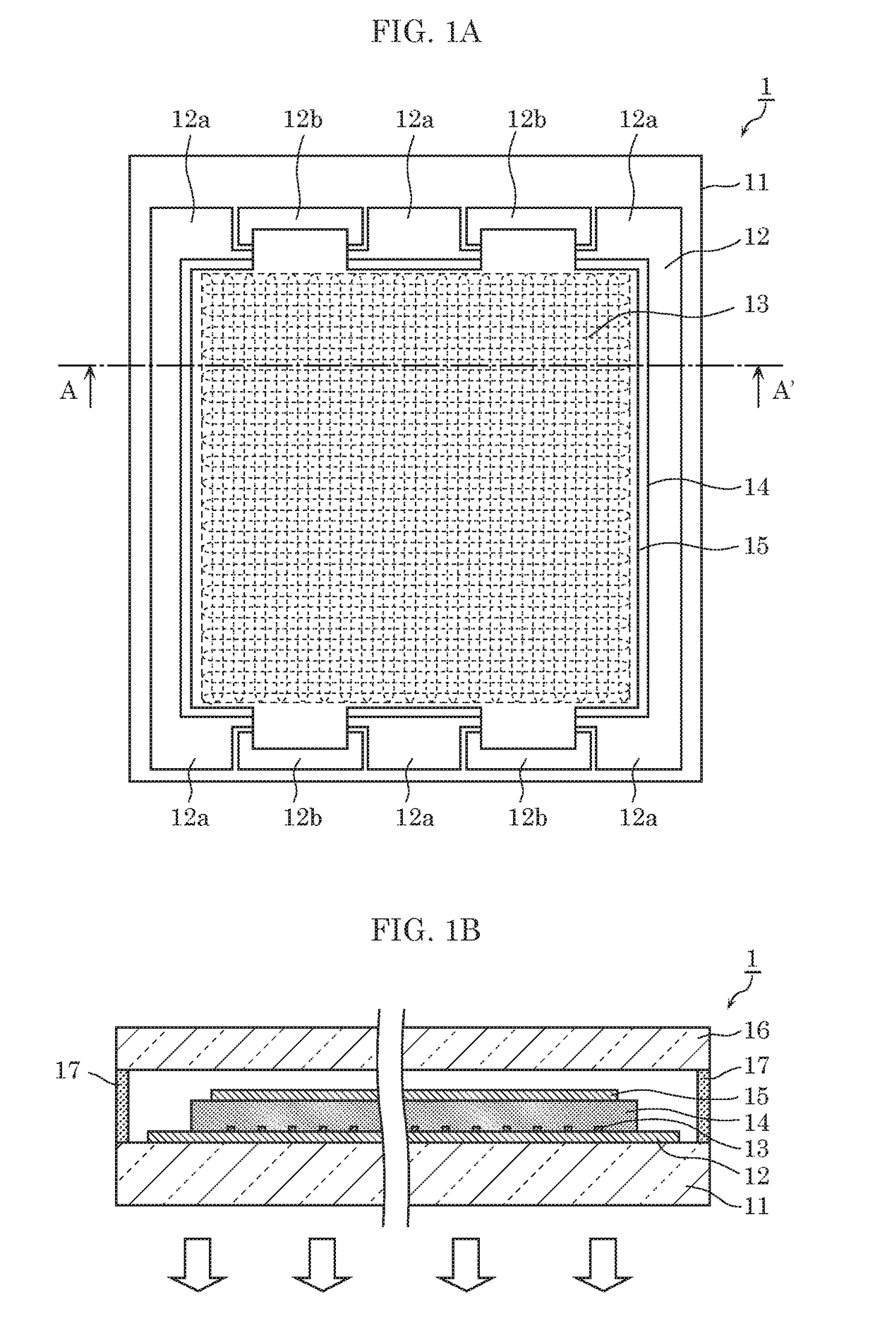
[0108]First, first electrode 12 made of an ITO film having a thickness of 150 nm and a sheet resistance of approximately 10 Ω / sq. was formed by magnetron sputtering on first substrate 11 made of a glass substrate having a substrate thickness of 0.7 mm. First electrode 12 was then cleaned with isopropyl alcohol and deionized water.

[0109]Next, liquid conductive material 130 (e.g., nano-silver paste (NPS-J) manufactured by Harima Chemicals Group, Inc.) was ejected onto first electrode 12 ...


PUM


Abstract

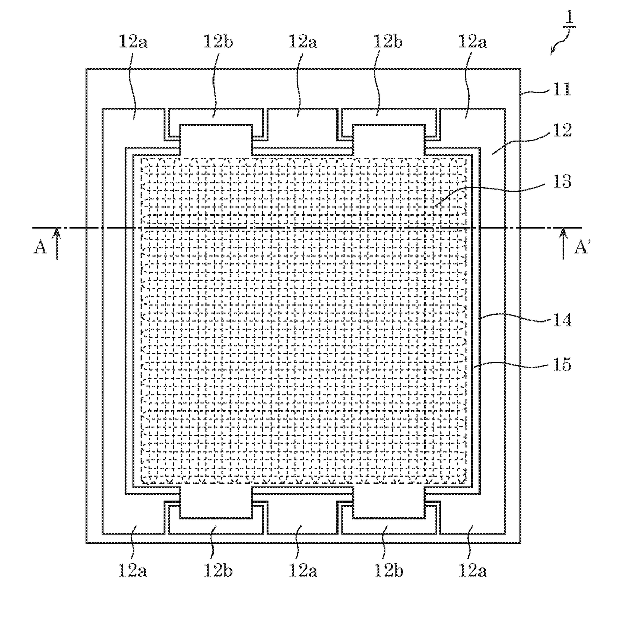
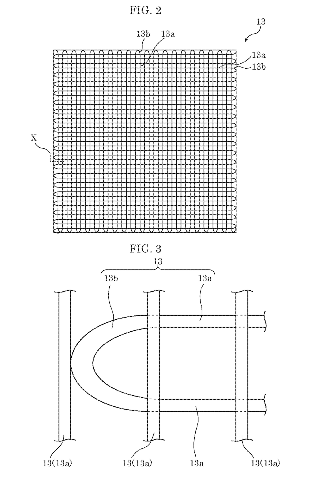
An organic EL panel includes a first substrate, a first electrode disposed on the first substrate, an organic layer including a light emitting layer and disposed on the first electrode, a second electrode disposed on the organic layer, and an auxiliary electrode stacked on the first electrode. The auxiliary electrode includes a linear portion and a curved portion, and the curved portion has a greater line width than the linear portion.

Description

TECHNICAL FIELD[0001]The present invention relates to an organic electroluminescent (EL) element and an organic EL element manufacturing method.BACKGROUND ART[0002]Consideration is being given to applying organic EL elements, such as organic EL panels, as high-efficiency surface light sources to various types of devices. For example, applying organic EL elements to devices, such as lightning fixtures, displays, and windows, is being expected.[0003]This type of organic EL element includes, for example, a translucent substrate, a transparent electrode made of, for example, indium tin oxide (ITO) and formed on the translucent substrate, an organic light emitting layer formed on the transparent electrode, and a reflecting electrode formed on the organic light emitting layer.[0004]Transparent conductive materials such as ITO that are used as materials for transparent electrodes generally have high resistivity. Thus, if in the above organic EL element, voltage is applied from an electrode...

Claims


Application Information

Patent Timeline
Patent Type & Authority Applications(United States)
IPC IPC(8): H01L51/52H01L51/50H01L51/56H01L51/00H10K99/00
CPCH01L51/5212H01L51/0096H01L51/0022H01L51/5221H01L51/56H01L51/5012Y02E10/549Y02P70/50H10K59/80521H10K59/80516H10K59/8052H10K50/814H10K50/11H10K50/82H10K71/00H10K71/611H10K77/10
Inventor YAMADA, TOMONORIIWAMOTO, NARIMASAICHIHARA, TSUTOMU
Owner SAMSUNG DISPLAY CO LTD
Learn More