Cardiac Pump

a heart pump and pump body technology, applied in the field of heart pump, can solve the problems of poor quality of life of patients, drug therapy and cardiac resynchronization treatment options, general failure of advanced heart failure treatment, etc., and achieve the effect of reducing preload force, increasing preload force, and reducing preload for

Active Publication Date: 2017-05-11
CALON CARDIO TECH
View PDF2 Cites 4 Cited by
  • Summary
  • Abstract
  • Description
  • Claims
  • Application Information

AI Technical Summary

Benefits of technology

[0017]The cardiac pump rotor may comprise a magnetic bearing engagement portion, for example a bore, opening, recess or projection, configured to receive the first magnetic bearing portion. The magnetic bearing engagement portion of the cardiac pump rotor may allow the position of first magnetic bearing portion to be adjusted through a range of positions. The range of positions may be defined by the extent by which the first magnetic bearing portion may be moved within, over and / or around the magnetic bearing engagement portion of the cardiac pump rotor. For example, when the first magnetic bearing portion is moved towards one end of the range of positions, the preload force may be reduced, and when the first magnetic bearing portion is moved towards the other end of the range of positions, the preload force may be increased.
[0018]The cardiac pump housing may comprise a magnetic bearing engagement portion, for example a bore, opening, recess or projection, configured to receive the second magnetic bearing portion. The magnetic bearing engagement portion of the cardiac pump housing may allow the position of second magnetic bearing portion to be adjusted through a range of positions. The range of positions may be defined by the extent by which the second magnetic bearing portion may be moved within, over and / or around the magnetic bearing engagement portion of the cardiac pump housing. For example, when the second magnetic bearing portion is moved towards one end of the range of positions, the preload force may be reduced, and when the second magnetic bearing portion is moved towards the other end of the range of positions, the preload force may be increased.

Problems solved by technology

Advanced heart failure is a major global health problem resulting in many thousands of deaths each year and those with the disease endure a very poor quality of life.
The treatment options for advanced heart failure, for example drug therapy and cardiac resynchronization (pacemakers), have generally proved unsuccessful and the only option remaining for the patients is heart transplantation.
Unfortunately, the number of donor hearts available only meets a fraction of the demand, leaving many people untreated.
However, for such plain bearing systems it may be difficult to ensure that the rotor is perfectly entrapped within the contact bearings.
Moreover, blood-immersed contact bearings of the prior art may be susceptible to proteinacious and other biological deposition in the bearings, and also the region proximate to and supporting structures around the contact bearings.
As a consequence, blood that passes through those small running clearances may be subjected to high levels of shear stress, which may have a detrimental effect on the cellular components of the blood, for example by causing haemolysis or platelet activation which may further lead to thrombosis.
However, due to the limitations resulting from Earnshaw's theorem, a passive magnetic bearing system requires another manner of support in at least one degree-of-freedom, for example active magnetic control, which may significantly increase the size and complexity of the design, and / or hydrodynamic suspension, which may increase the requirements with regard to manufacturing tolerances or introduce blood damage.

Method used


Image

  • Cardiac Pump
  • Cardiac Pump
  • Cardiac Pump

Examples


Embodiment Construction

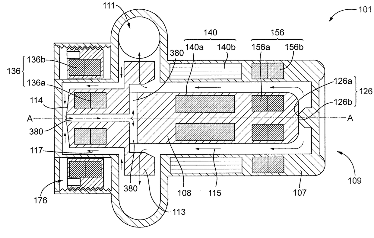
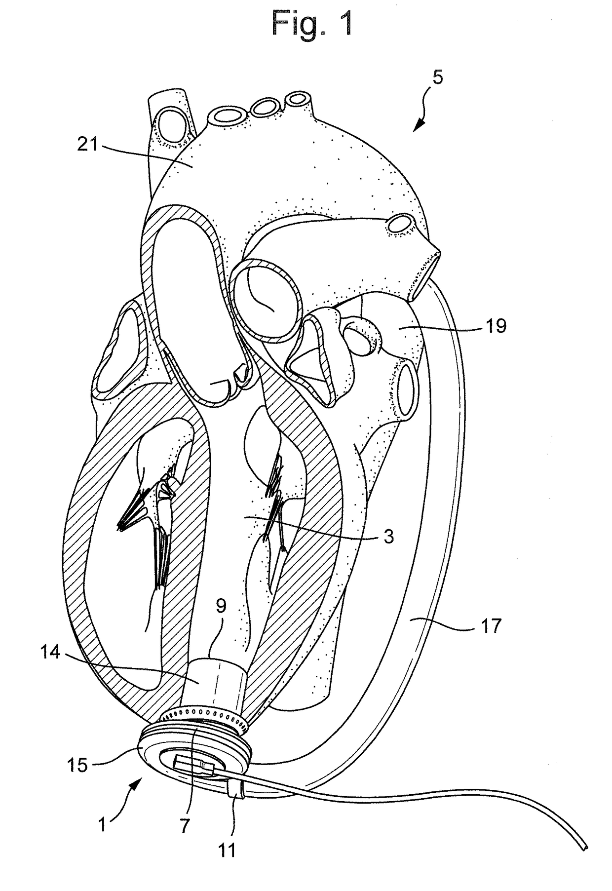
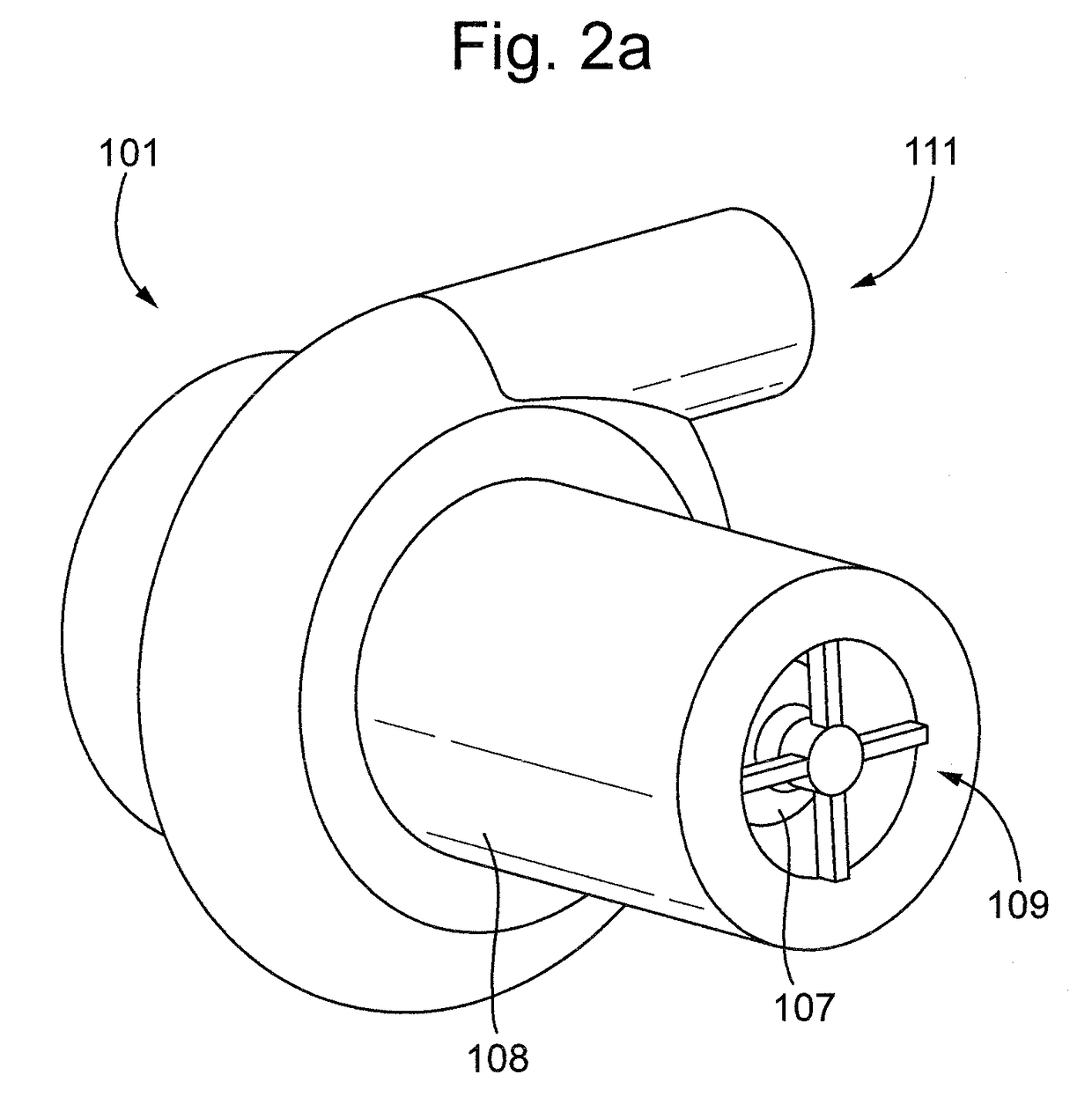
[0037]FIG. 1 depicts a cardiac pump 1 for the treatment of heart failure, for example a Ventricular Assist Device (VAD), in an implanted configuration in the left ventricle 3 of a heart 5. The cardiac pump 1 comprises a cardiac pump housing 7 comprising an inlet 9 for blood and an outlet 11 for blood. The cardiac pump 1 comprises a cardiac pump rotor disposed at least partially within the cardiac pump housing 7. The cardiac pump rotor is supported, for example rotatably supported, by way of one or more bearing assemblies, as described below.

[0038]The cardiac pump 1 comprises an inflow cannula 14 situated at least partially inside the left ventricle 3 and a pumping chamber 15 situated outside of the heart 5. The inflow cannula 14 extends between the pumping chamber 15, through the wall of the left ventricle 3 into the chamber of the left ventricle 3, so that the inlet 9 is situated completely within the left ventricle 3. The pumping chamber 15 is situated on the apex of the left vent...


PUM


Abstract

A cardiac pump includes a plain bearing assembly having a first plain bearing portion that is coupled to a cardiac pump rotor and a second plain bearing portion that is coupled to a cardiac pump housing. The plain bearing assembly is configured to rotatably support the cardiac pump rotor within the cardiac pump housing in at least an axial direction of the cardiac pump rotor. A magnetic bearing assembly includes a first magnetic bearing portion that is coupled to the cardiac pump rotor and a second magnetic bearing portion that is coupled to the cardiac pump housing. The magnetic bearing assembly is configured to rotatably support the cardiac pump rotor within the cardiac pump housing in a radial direction of the cardiac pump rotor and bias the cardiac pump rotor in the axial direction such that the magnetic bearing assembly provides a preload force to preload the plain bearing assembly.

Description

[0001]This disclosure relates to a cardiac pump having a plain bearing assembly and a magnetic bearing assembly and particularly, but not exclusively, relates to a cardiac pump comprising a plain bearing assembly configured to support a cardiac pump rotor, and a magnetic bearing assembly configured to support the cardiac pump rotor and provide a preload force to preload the plain bearing assembly.BACKGROUND[0002]Advanced heart failure is a major global health problem resulting in many thousands of deaths each year and those with the disease endure a very poor quality of life. The treatment options for advanced heart failure, for example drug therapy and cardiac resynchronization (pacemakers), have generally proved unsuccessful and the only option remaining for the patients is heart transplantation. Unfortunately, the number of donor hearts available only meets a fraction of the demand, leaving many people untreated.[0003]Ventricular Assist Devices (VAD) have been gaining increased a...

Claims


Application Information

Patent Timeline
Patent Type & Authority Applications(United States)
IPC IPC(8): A61M1/10A61M60/178A61M60/237A61M60/419A61M60/82
CPCA61M1/1015A61M2207/00A61M1/1031A61M1/1013A61M60/82A61M60/422A61M60/148A61M60/419A61M60/237A61M60/178F04D13/0633F04D29/041F04D29/048F04D29/042
Inventor FOSTER, GRAHAM
Owner CALON CARDIO TECH
Why Eureka
Try Eureka