Methods for drilling multiple parallel wells with passive magnetic ranging

a technology of magnetic range and parallel wells, applied in the direction of directional drilling, survey, borehole/well accessories, etc., can solve the problem that the offset well does not provide a magnetic field

Active Publication Date: 2017-05-18
BAKER HUGHES INC
View PDF7 Cites 17 Cited by
  • Summary
  • Abstract
  • Description
  • Claims
  • Application Information

AI Technical Summary

Problems solved by technology

In these instances, the offset well does not provide a magnetic field that can be sensed at the drill string in the new well.

Method used


Image

  • Methods for drilling multiple parallel wells with passive magnetic ranging
  • Methods for drilling multiple parallel wells with passive magnetic ranging
  • Methods for drilling multiple parallel wells with passive magnetic ranging

Examples


Embodiment Construction

[0017]A detailed description of one or more embodiments of the disclosed apparatus and method are presented herein by way of exemplification and not limitation with reference to the Figures.

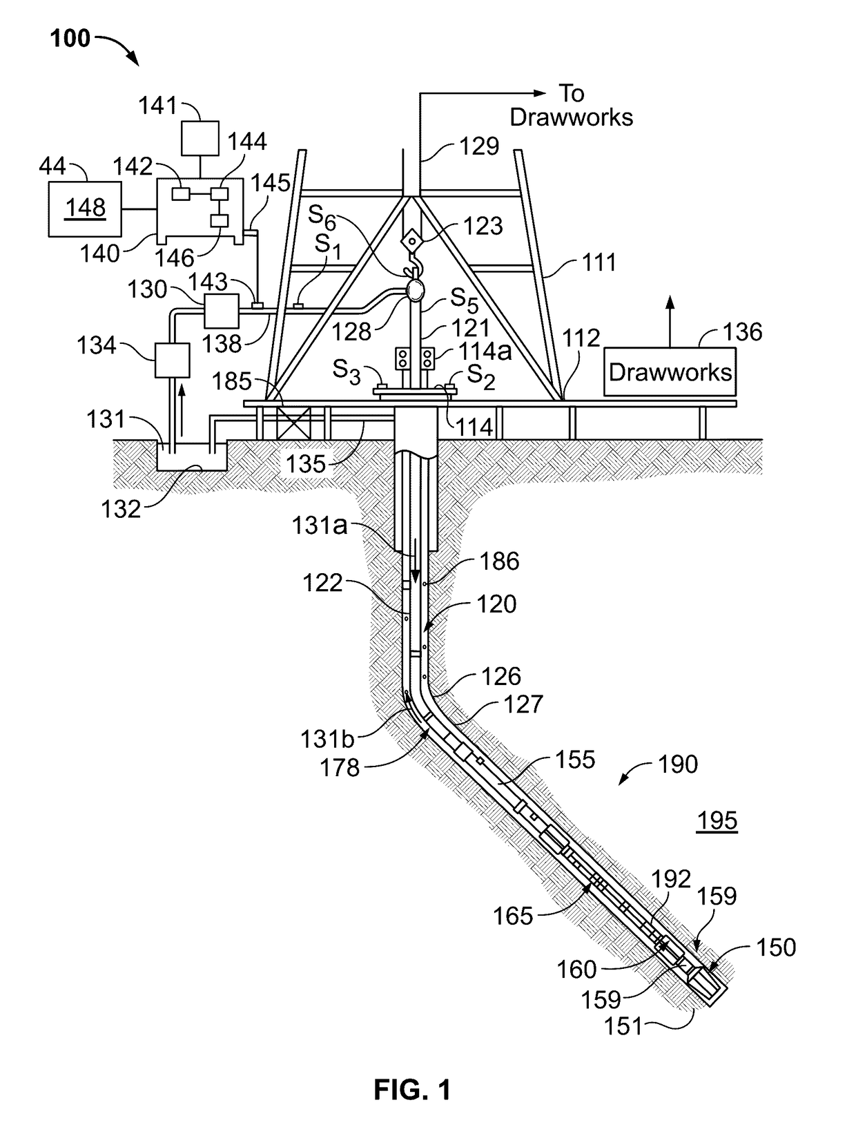
[0018]FIG. 1 is a schematic diagram of an exemplary drilling system 100 that includes a drill string having a drilling assembly attached to its bottom end that includes a steering unit according to one embodiment of the disclosure. FIG. 1 shows a drill string 120 that includes a drilling assembly or bottomhole assembly (“BHA”) 190 conveyed in a borehole 126, also referred to herein as a well or wellbore. The drilling system 100 includes a conventional derrick 111 erected on a platform or floor 112 which supports a rotary table 114 that is rotated by a prime mover, such as an electric motor (not shown), at a desired rotational speed. A tubing (such as jointed drill pipe) 122, having the drilling assembly 190 is attached at its bottom end extends from the surface to the bottom 151 of the borehole 1...


PUM


Abstract

A system and method for drilling a second well with respect to a first well is disclosed. A first drill string having a known magnetic signature is disposed at a first depth in the first well. A second drill string is used to drill the second well. The second drill string includes a magnetometer that obtains a magnetic measurement of the first drill string during drilling of the second well. A processor uses the obtained magnetic measurement and the magnetic signature of the first drill string to steer the second drill string to drill the second well.

Description

CROSS REFERENCE TO RELATED APPLICATIONS[0001]This application claims priority from U.S. Provisional Application Ser. No. 62 / 255,924, filed Nov. 16, 2015, the contents of which are incorporated herein by reference in their entirety.BACKGROUND[0002]The present disclosure relates to directional drilling and, in particular, to a method of determining a location of a well drilled with respect to an offset well using passive magnetic ranging.[0003]Efficient extraction of mineral ores in a deep narrow vein can be obtained by drilling multiple parallel open-hole wells at close spacing. Also, extracting petroleum from a reservoir often involves drilling multiple parallel horizontal wells at fairly close spacings to efficiently stimulate and drain the reservoir. In a simple field development scenario, parallel horizontal wells are planned, drilled and completed with sufficient spacing between them that the adjacent well's steel casing is too far away to interfere with the undisturbed earth's ...

Claims


Application Information

Patent Timeline
Patent Type & Authority Applications(United States)
IPC IPC(8): E21B47/022E21B47/024G01V3/26E21B7/04
CPCE21B47/022E21B7/04E21B47/024E21B43/2406E21B44/00E21B47/18G01V3/26E21B47/092
Inventor ESTES, ROBERT A.LEAL, CATALINA
Owner BAKER HUGHES INC
Why Eureka
Try Eureka