Optical processing apparatus and light source luminance adjustment method thereof

a technology of optical processing and luminance adjustment, which is applied in the direction of image enhancement, instruments, television systems, etc., can solve the problems of poor quality, limited frame rate of optical processing apparatus, and adverse effects

Active Publication Date: 2017-05-18
PIXART IMAGING INC
View PDF11 Cites 62 Cited by
  • Summary
  • Abstract
  • Description
  • Claims
  • Application Information

AI Technical Summary

Benefits of technology

[0010]To improve the aforesaid problems, the present invention provides an optical processing apparat

Problems solved by technology

For example, for some optical processing apparatuses, images that are too bright or too dark will have an adverse effect on the result of the subsequent determination and be considered to have poor quality.
However, when this practice is adopted

Method used


Image

  • Optical processing apparatus and light source luminance adjustment method thereof
  • Optical processing apparatus and light source luminance adjustment method thereof
  • Optical processing apparatus and light source luminance adjustment method thereof

Examples


first embodiment

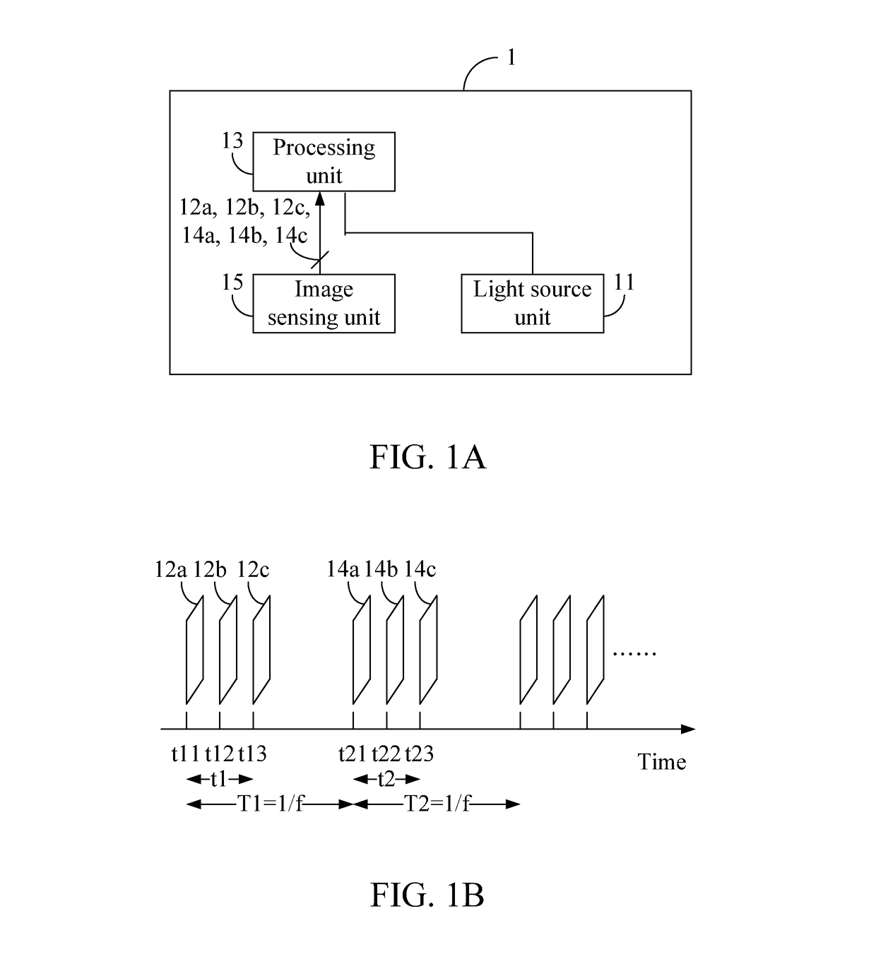
[0027]the present invention is an optical processing apparatus 1, a schematic view of which is depicted in FIG. 1A. The optical processing apparatus 1 comprises a light source unit 11, a processing unit 13, and an image sensing unit 15. The processing unit 13 is electrically connected to the light source unit 11 and the image sensing unit 15.

[0028]The light source unit 11 may be a light emitting diode (LED) or some other light source units well-known to those of ordinary skill in the art. The processing unit 13 may be of any various processors, central processing units (CPUs), microprocessors, or other computing devices well-known to those of ordinary skill in the art. The image sensing unit 15 may be a complementary metal oxide semiconductor (CMOS) light sensing unit or an image sensing unit well-known to those of ordinary skill in the art.

[0029]When the optical processing apparatus 1 is powered on, the light source unit 11 generates a beam of light (not shown) of identifiable spec...

third embodiment

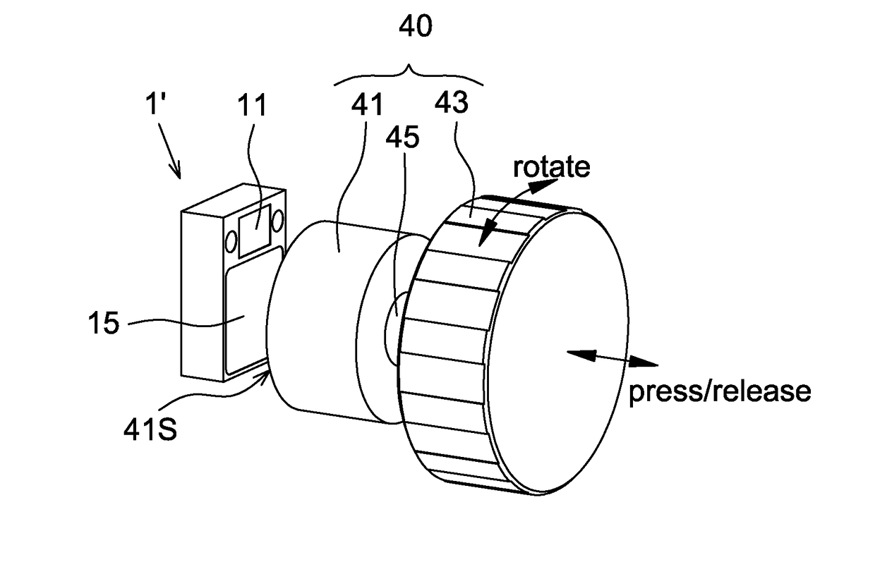
[0063]Referring to FIG. 4, it is an application embodiment of an optical processing apparatus 1′ according to the present disclosure in which the optical processing apparatus 1′ is adapted to detect a pressing state and a rotational displacement of a watch crown 40. In FIG. 4, the watch crown 40 is shown to include a rotary shaft 41, a rotary part 43, and a connection part 45 for connecting the rotary shaft 41 and the rotary part 43. The function and structure of a watch crown is known to the art and thus details thereof are not described therein. It should be mentioned that although FIG. 4 takes a watch crown 40 as an example for illustrating a button, the present disclosure is not limited thereto. The button may be other types having a proper structure as long as it can be pushed / pulled and rotated by a user, and has a surface to be illuminated and captured by the optical processing apparatus 1′.

[0064]Referring to FIG. 5 together, FIG. 5 is a block diagram of an optical processing...


PUM


Abstract

An optical processing apparatus and a light source luminance adjustment method adapted to detect a rotational displacement and a pressing state are provided. The optical processing apparatus includes a light source unit, a processing unit, and an image sensing unit, wherein the processing unit is electrically connected to the light source unit and the image sensing unit. The light source unit provides a beam of light. The processing unit defines a frame rate, defines a plurality of time instants within a time interval, and sets the light source unit to a luminance value at each of the time instants. A length of the time interval is shorter than the reciprocal of the frame rate. The luminance values are different and are within a range. The image sensing unit captures an image by an exposure time length at each of the time instants, wherein the exposure time lengths are the same.

Description

CROSS-REFERENCES TO RELATED APPLICATIONS[0001]This application a continuation-in-part application of U.S. patent application Ser. No. 15 / 240,120 filed on, Aug. 18, 2016, and the entire contents of which are incorporated herein by reference. The Ser. No. 15 / 240,120 application is a divisional application of U.S. patent application Ser. No. 13 / 959,225, filed on Aug. 5, 2013, and the entire contents of which are incorporated herein by reference. The Ser. No. 13 / 959,225 application claimed the benefit of the date of the earlier filed Taiwan Patent Application No. 102104112 filed on Feb. 4, 2013, priority to which is also claimed herein, and the contents of which are also incorporated by reference herein.BACKGROUND OF THE INVENTION[0002]Field of the Invention[0003]The present invention relates to an optical processing apparatus, a light source luminance adjustment method, and a non-transitory computer readable medium thereof. More particularly, the present invention relates to an optical...

Claims


Application Information

Patent Timeline
IPC IPC(8): G06F3/03G06T7/00G06F3/0362
CPCG06F3/0312G06F3/0362G06T2207/10144H04N5/2353G06T2207/30168G06T7/0002G06F3/0304G06F1/163G06F1/169G04G21/025H04N23/743H04N23/71H04N23/73H04N23/74G04G21/00
Inventor CHEN, CHUN-WEICHUNG, CHING-LIN
Owner PIXART IMAGING INC
Why Eureka
Try Eureka