Plasma device driven by multiple-phase alternating or pulsed electrical current

a technology of multiple-phase alternating or pulsed current, which is applied in the direction of basic electric elements, electrical discharge tubes, electrical apparatus, etc., can solve the problems of unfavorable linear hollow cathode operation, degree of uniformity, and use of two-phase power in hollow cathode plasma sources, so as to improve the time of active plasma generation, improve the deposition rate, and improve the operational life of the plasma source

Inactive Publication Date: 2017-05-18
AGC FLAT GLASS NORTH AMERICA INC +2
View PDF2 Cites 7 Cited by
  • Summary
  • Abstract
  • Description
  • Claims
  • Application Information

AI Technical Summary

Benefits of technology

[0007]Advantages of embodiments of the present invention include, but are not limited to, improved operational life of a plasma source, improved deposition rate, and improved time of active plasma generation. Additionally, embodiments of the present invention result in increased disassociation energy in the precursor gas or gasses used, which leads to denser coatings when using plasma-enhanced chemical vapor deposition.

Problems solved by technology

Although some types of plasma sources using direct current can effectively utilize magnets to generate a uniform plasma, this cannot be done with linear hollow cathodes.
However, a high degree of uniformity (not achievable by the use of direct current in a linear hollow cathode plasma source) is necessary for many applications, such as coating glass using plasma-enhanced chemical vapor deposition.
However, the use of two-phase power in hollow cathode plasma sources has some disadvantages.
Another disadvantage is that there is significant wear on the plasma source due to the use of the two-phase power source, which decreases the operational life of the plasma source.

Method used


Image

  • Plasma device driven by multiple-phase alternating or pulsed electrical current
  • Plasma device driven by multiple-phase alternating or pulsed electrical current
  • Plasma device driven by multiple-phase alternating or pulsed electrical current

Examples


Embodiment Construction

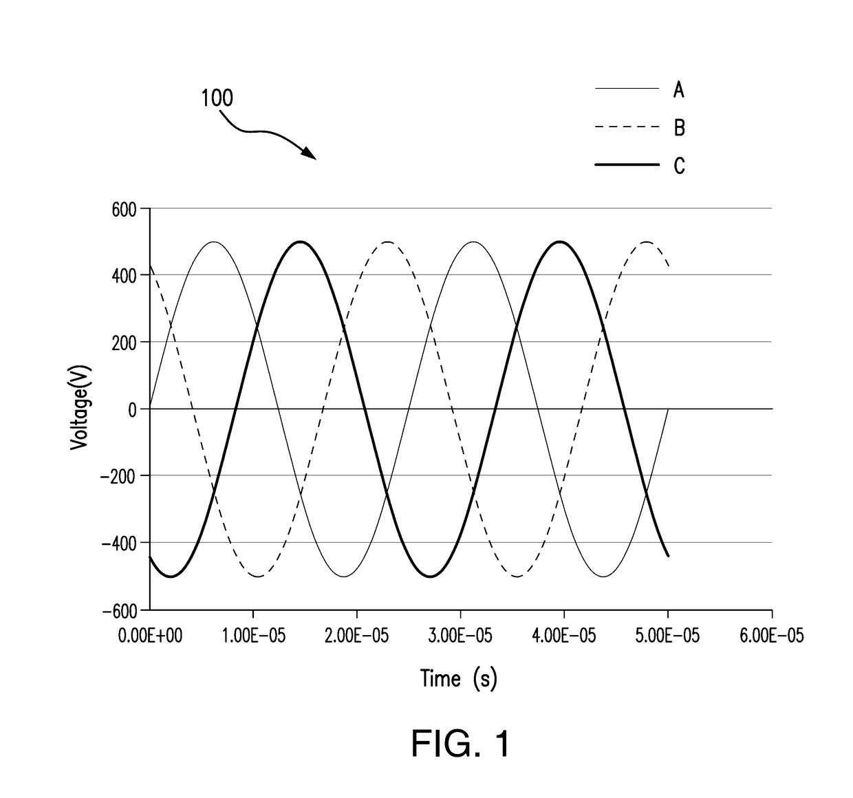
[0035]Consider a sine wave A sin 2πft+φ, where A is the amplitude, f is the frequency, and φ is the phase angle. The phase angle φ specifies where the oscillation is at time t=0. With respect to two sine waves A1 sin 2πft+φ1 and A2 sin 2πft+φ2, the phase difference between the two waves is defined as the difference of phase angles φ2−φ1. Note that this definition makes the phase difference depend on which wave is considered the first wave and which wave is considered the second wave. That is, if the order is changed, the sign of the phase difference will change. The wave that has a larger phase angle is said to be the leading wave, and the wave with a smaller phase angle is said to be the lagging wave. If the leading wave is considered to be the first wave, and the phase difference is φ, then considering the lagging wave as the first wave will lead to a phase difference of −φ. Generally this specification will not treat the sign of the phase difference with much significance, and wi...


PUM


Abstract

A plasma source is provided. The plasma source includes at least three hollow cathodes, including a first hollow cathode, a second hollow cathode, and a third hollow cathode, each hollow cathode having a plasma exit region. The plasma source includes a source of power capable of producing multiple output waves, including a first output wave, a second output wave, and a third output wave, wherein the first output wave and the second output wave are out of phase, the second output wave and the third output wave are out of phase, and the first output wave and the third output wave are out of phase. Each hollow cathode is electrically connected to the source of power such that the first hollow cathode is electrically connected to the first output wave, the second hollow cathode is electrically connected to the second output wave, and the third hollow cathode is electrically connected to the third output wave. Electrical current flows between the at least three hollow cathodes that are out of electrical phase. The plasma source is capable of generating a plasma between the hollow cathodes.

Description

BACKGROUND OF THE INVENTION[0001]Hollow cathode plasma sources are commonly used in the art for coating and surface treatment applications. These plasma sources comprise one or more hollow cathodes electrically connected to a source of power. Several different types of hollow cathodes may be used in these plasma sources, including point sources or linear hollow cathodes.[0002]Power sources used in hollow cathode plasma sources are typically configured to supply one of direct current, alternating current, or pulsed current (i.e., current having a square or rectangular waveform where the duty cycle is less than 100%) to the hollow cathodes. Bipolar power sources (i.e. two phase power supplies) are currently used to provide alternating or pulsed current to a hollow cathode plasma source.[0003]The use of direct current during operation of a linear hollow cathode plasma source causes plasma to be generated primarily in a single area, rather than throughout the entire length of the linear...

Claims


Application Information

Patent Timeline
Patent Type & Authority Applications(United States)
IPC IPC(8): H01J37/32
CPCH01J37/32596H01J37/32568
Inventor CHAMBERS, JOHNMASCHWITZ, PETER
Owner AGC FLAT GLASS NORTH AMERICA INC
Why Eureka
Try Eureka