Method and device for an error correction of trans

Inactive Publication Date: 2017-05-18
TECHN UNIV KAISERSLAUTERN
View PDF5 Cites 2 Cited by
  • Summary
  • Abstract
  • Description
  • Claims
  • Application Information

AI Technical Summary

Benefits of technology

[0029]In a further preferred embodiment, in step (b), at least one type II error position, preferably more than one type II error positions, may be determined by storing at least one column, preferably more than one column, of the diagonalized parity-check matrix H′ as at least one stored column and comparing the syndrome vector with the at least one stored column. Alternatively or in addition, it may be preferable to store at least one sum of at least one column, preferably more than one column, of the diagonalized parity-check matrix H′ with the syndrome vector as at least one stored column, and/or to store at least one sum of at least two columns of the columns of the diagonalized parity-check matrix H′ as at least one stored column. In particular, both the storing of more than one stored column and the comparing of the syndrome vector with the at least one stored column may be performed simultaneously, which may result in a considerable enhancement of the computation time as required for determining more than one type II error positions within the parity-check matrix H.
[0030]In a fur

Problems solved by technology

However, at least one error may occur during a data transmission from a transmitter as being located at the first location to a receiver as being located at the second location, owing to a fact that the data transmission is, in practice, performed via a transmission channel, which comprises a transmission medium, such as air or a wire, wherein the transmission medium may be unreliable subject to noise and/or other disturbances and may be, thus, produce at least one erroneous data bit, i.e. a data bit which may be different in the receiver with respect to the transmitter.
Within this regard, the main challenge of the decoding procedure comprises actually determining at least one error position within the data

Method used


Image

  • Method and device for an error correction of trans
  • Method and device for an error correction of trans
  • Method and device for an error correction of trans

Examples


Embodiment Construction

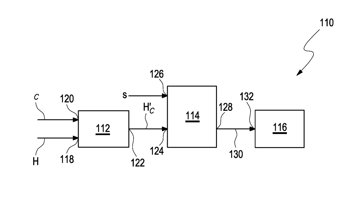
[0055]FIG. 1 shows a schematic view of a preferred embodiment of an error correction device 110 being capable of an error correction of transmitted data according to the present invention. Herein, the transmitted data are encoded in a block code, wherein the block code comprises a number of data bits and an additional number of redundant bits, wherein the block code is described by a parity-check matrix H, wherein the parity-check matrix H comprises a number of columns c=c1, c2, c3, . . . cn, , wherein 1, 2, 3 . . . , n denotes the corresponding number of the respective column, wherein the respective columns are related to the data bits of the block code. In this particular embodiment, the error correction device 110 comprises three distinctive separate parts, i.e. a diagonalization unit 112, an error detection unit 114, and an error correction unit 116.

[0056]Herein, the diagonalization unit 112 is adapted for diagonalizing at least one column c of a parity-check matrix H according ...


PUM


Abstract

The present invention relates to a method and a device for an error correction of transmitted data. For this purpose, the transmitted data are encoded in a block code, wherein the block code comprises a number of data bits and an additional number of redundant bits. Herein the block code is described by a parity-check matrix H, wherein columns of the parity-check matrix Hare inherently related to the data bits of the block code. The method according to the present invention comprises the following steps: (a) diagonalizing the parity-check matrix H, with respect to at least one column of the parity-check matrix H, into a diagonalized parity-check matrix H′, wherein the diagonalized parity-check matrix H′ is related to the block code and to the at least one column; (b) determining at least one error position (130) in the block code by using the diagonalized parity-check matrix H′ and a syndrome vector, wherein the syndrome vector is related to the data bits in the block code; (c) performing the error correction of the transmitted data at the at least one error position (130) in the block code. The present method and device allow providing communication channels with increased reliability and enhanced correction capability at reduced complexity, and is generally applicable to all known block codes, such as turbo, LDPC, BCH, or Reed-Solomon codes.

Description

FIELD OF THE INVENTION[0001]The present invention relates to a method and to a device as well as to a use of a device for an error correction of transmitted data, wherein the transmitted data are encoded in a block code, wherein the block code comprises a number of data bits and an additional number of redundant bits, wherein the block code is described by a parity-check matrix H, wherein columns of the parity-check matrix H are related to the data bits of the block code. The invention further relates to a computer program for performing the mentioned method as well as to a data carrier having a data structure stored thereon, which, after loading into a computer or a computer network, is capable of executing the method according to the present invention.RELATED ART[0002]Digital communication systems according to the state of the art are capable of transmitting data in form of data bits from a first location to a second location. However, at least one error may occur during a data tr...

Claims


Application Information

Patent Timeline
IPC IPC(8): H03M13/11H03M13/00
CPCH03M13/616H03M13/1148H03M13/1102H03M13/1515H03M13/152H03M13/2963H03M13/3723H03M13/3746H03M13/451H03M13/6561
Inventor SCHOLL, STEFANWEHN, NORBERT
Owner TECHN UNIV KAISERSLAUTERN
Why Eureka
Try Eureka