A dental light irradiation device

a light irradiation device and dental technology, applied in the field of dental light irradiation devices, can solve the problems of insufficient hardening of dental materials, insufficient durability of dental fillings, and each of the different parts of dental materials to be exposed to light for a shorter time, so as to maximize the amount of light transmittable through the lens, excellent balance, and high light intensity

Inactive Publication Date: 2017-05-25
3M INNOVATIVE PROPERTIES CO
View PDF23 Cites 0 Cited by
  • Summary
  • Abstract
  • Description
  • Claims
  • Application Information

AI Technical Summary

Benefits of technology

[0008]The device of the invention comprises a light source and means for collimating light emitted from the light source. The light collimating means comprises a (preferably a single or only one) plano-convex lens. Such a plano-convex lens has a convex side and an opposite planar side. The plano-convex lens is oriented with the planar side toward the light source. The light collimating means comprises further a reflector. The reflector is formed by a hollow ring-shaped structure having an inner conical and reflective surface. Hence, the reflector operates based on surface reflection as opposed to total reflection. Thus, losses of light may be minimized.
[0018]In one embodiment the light collimating means consists only of the single plano-convex lens and the reflector. The device is advantageous in that it helps maximizing the reliability of light-hardening of a dental light-hardenable material in a patient's mouth. Other than prior art devices which aim for maximizing the light intensity by focusing light toward a small area, the device of the present invention implements optics which collimates diverging light toward parallel light. It has been found that the accuracy of positioning the device of the invention relative to the material to be hardened is less critical compared to prior art devices, based on a similar quality of the hardened dental material. In other words although some prior art devices allow for hardening of dental materials at superb quality if positioned accurately, the same result can be achieved with the device of the invention if positioned at higher positioning tolerances. In an embodiment the output side is formed by a planar or generally planar end face of the light guide.
[0023]In one preferred embodiment the center of the light source is positioned at (or substantially at) the effective focal length of the (plano-convex) lens. In other words the light source is positioned with its center offset from the so-called “rear principle plane” of the (plano-convex) lens by the effective focal length. In a (plano-convex) lens that has two principle planes the “rear principle plane” refers to the principle plane which is located closer to the light source. It was found that a device implementing such a configuration (comprising the reflector and the lens) provides a more uniform light intensity profile of the light output than the same device in which the light source is positioned outside the effective focal length of the lens. Further such a configuration provides an excellent balance between high light intensity and uniform light distribution.
[0024]In one embodiment the reflective tube has a cylindrical inner reflective shape. The reflective tube helps capturing any light that is unintentionally diffused in the light collimating means and / or by the light source, for example from inaccuracies or slight impurities in the light collimating means, the light source and / or the materials these components are made of. It was found the reflective tube helps maximizing the uniformity of the light beam profile and light intensity.
[0028]In one embodiment the light guide and the housing are attachable with each other by a magnetic coupling. Thus the light guide and the housing may be easily detached and re-attached by a user.
[0030]In one embodiment the light guide extends at least partially at a generally rectangular cross-section. For example at least the light output may have a rectangular shape to approximately match with the shape on a human molar tooth. This may provide guidance to a user for appropriately positioning the light output to a tooth filled with a light hardenable dental material. Therefore this embodiment may help further maximizing the reliability of light-hardening of a dental light-hardenable material.

Problems solved by technology

This may however cause each of the different portions of the dental material to get exposed to the light for a shorter time than pre-selected.
This may further result in insufficient hardening of the dental material and thus to an insufficient durable dental filling.
This may however cause the dental material to heat up and cause postoperative diseases for the patient.
Further this may cause the dental material to overharden and to become brittle.

Method used


Image

  • A dental light irradiation device
  • A dental light irradiation device
  • A dental light irradiation device

Examples


Embodiment Construction

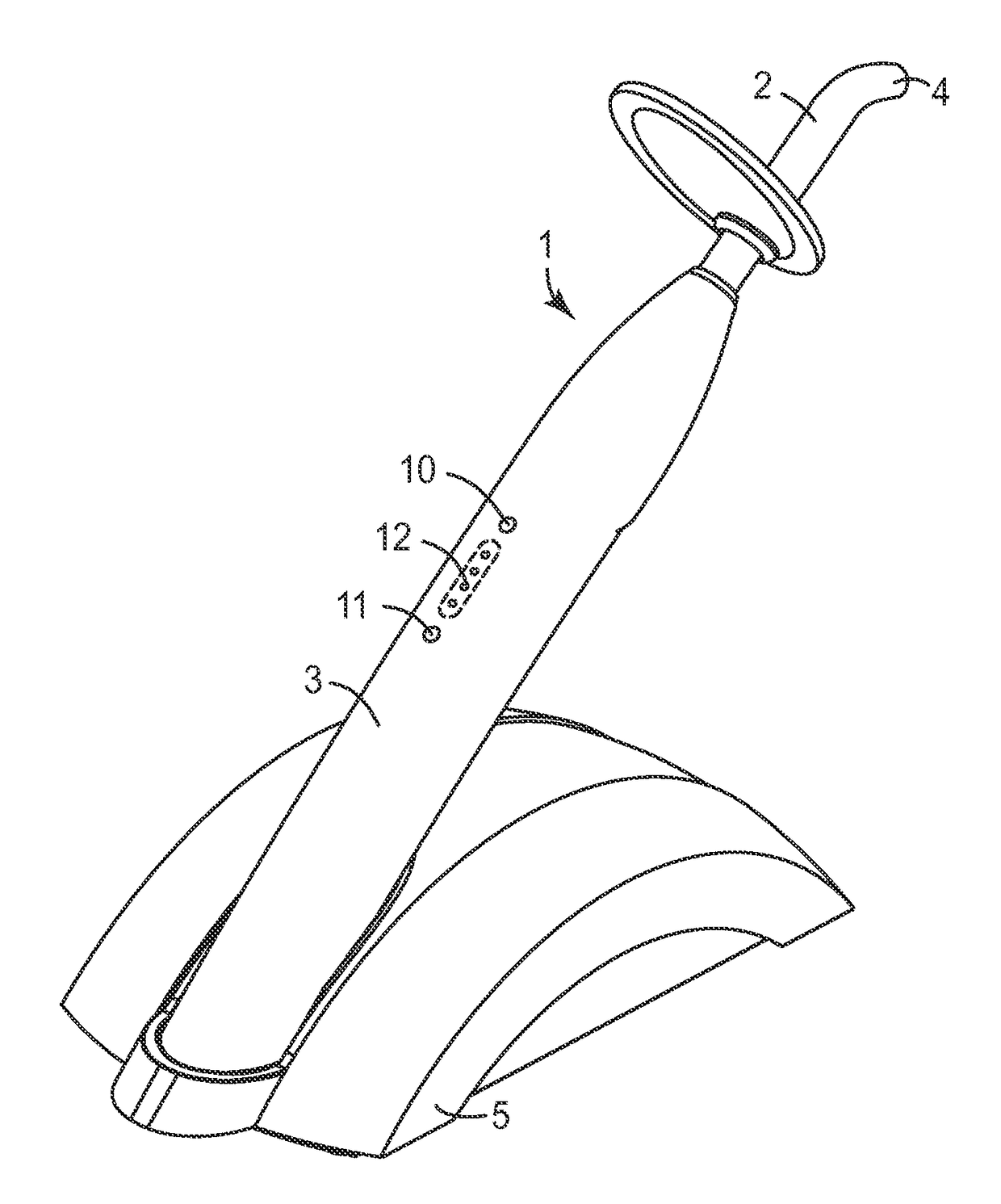
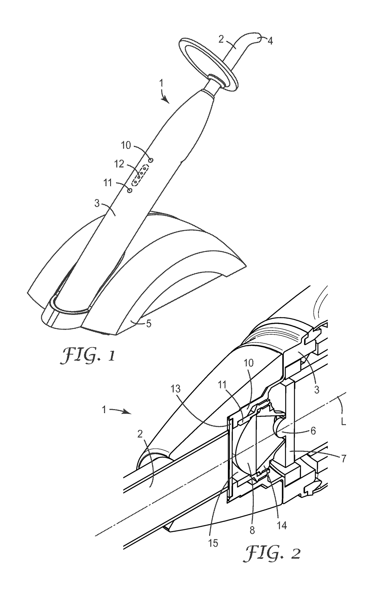
[0043]FIG. 1 shows an exemplary dental light irradiation device 1. The device 1 has a housing 3, and a light guide 2 with a light output 4. The dental light irradiation device 1 of the example is removably placed in a base 5. The device 1 is battery powered and therefore separable from the base 5 without the need of a permanent wired connection between the device 1 and the base 5. The base 5 has a power supply for charging the device 1 when the device is placed in the base 5. Such a power supply may comprise physical electric contacts for contacting corresponding contacts of the device 1, or an induction coupling for coupling with a corresponding induction coupling in the device 1. The exemplary dental light irradiation device 1 further has two buttons, an on / off button 10 and a selector button 11. The selector button 11 is typically used to pre-select a time period for which the device operates as soon as it is switched on via the on / off button 10. Therefore the device 1 can be use...


PUM


Abstract

A dental light irradiation device is adapted to emit blue light. The device has a light source, means for collimating light emitted from the light source, and a light guide. The light collimating means comprising:—a plano-convex lens oriented with the planar side toward the light source, and—a reflector formed by a hollow ring-shaped structure having an inner conical and reflective surface. The reflector is arranged such that its inner cross-section widens toward the lens and extends over the entire distance between the planar side of the lens and the light source. The light source being positioned substantially at the effective focal length of the lens, and the light guide having an input side for receiving light emitted from the light source and an output side for the light.

Description

FIELD OF THE INVENTION[0001]The invention relates to a dental light irradiation device, and in particular to a dental light irradiation device which is adapted for emitting light in a working area at a light intensity distribution within a pre-determined minimized range.BACKGROUND ART[0002]Light-curable or light-hardenable materials are widely used in dentistry for the restoration of teeth, for example for filling a cavity in a tooth. Such materials typically can be made to provide optical characteristics that resemble those of natural teeth, which makes those materials a favored alternative to unpleasant looking amalgam materials, for example.[0003]Light-hardenable materials often include a polymerizable matrix material and filler materials including colorants, and may initially be generally soft or flowable so that they can be applied in a desired location and shape. For example, for restoration of a tooth the dental material may be filled into a tooth cavity and shaped so that th...

Claims


Application Information

Patent Timeline
Patent Type & Authority Applications(United States)
IPC IPC(8): A61C13/15G02B3/04G02B19/00
CPCA61C19/004G02B3/04G02B19/0061G02B19/0028G02B3/02G02B27/30G02B19/0052
Inventor WELKER, STEFANYUN, ZHISHENGSCHMID, RUDOLFGERLACH, KORBINIAN
Owner 3M INNOVATIVE PROPERTIES CO
Why Eureka
Try Eureka