
Novel engine controlled by combustion reaction path and regulating method thereof

a technology of combustion reaction path and combustion reaction path, which is applied in the direction of combustion engine, machine/engine, charge feed system, etc., to achieve the effects of high effectiveness and clean combustion

Active Publication Date: 2017-05-25
TIANJIN UNIV
View PDF5 Cites 11 Cited by
  • Summary
  • Abstract
  • Description
  • Claims
  • Application Information

AI Technical Summary

Benefits of technology

The present invention provides a novel engine controlled by combustion reaction path that has high efficiency and energy saving during operation. The engine realizes fuel reforming inside the cylinder, concentration stratification of mixed gas, and reactive stratified combustion without needing extra catalytic devices. The regulating method of the present invention can regulate the EGR value and exhaust gas exhausted from the flexible cylinder. The engine can compress, heat, and reform the fuel injected from the reforming cylinder injector, achieving high effectiveness and clean combustion. The present invention just adopts simple oxidation reaction post-treatment device and can meet the requirement of EuroVI emission regulation.

Problems solved by technology

Furthermore, the first EOV unidirectional regulates the inlet air flow of the main air inlet pipe to go through reforming cylinder air inlet pipe and the working cylinder air inlet pipe.

Method used


Image

  • Novel engine controlled by combustion reaction path and regulating method thereof
  • Novel engine controlled by combustion reaction path and regulating method thereof
  • Novel engine controlled by combustion reaction path and regulating method thereof

Examples


Embodiment Construction

[0047]The present invention will be further described in detail with reference to specific embodiments. The embodiment described below is intended to be explanatory and illustrative only, and is not used for limiting the present invention.

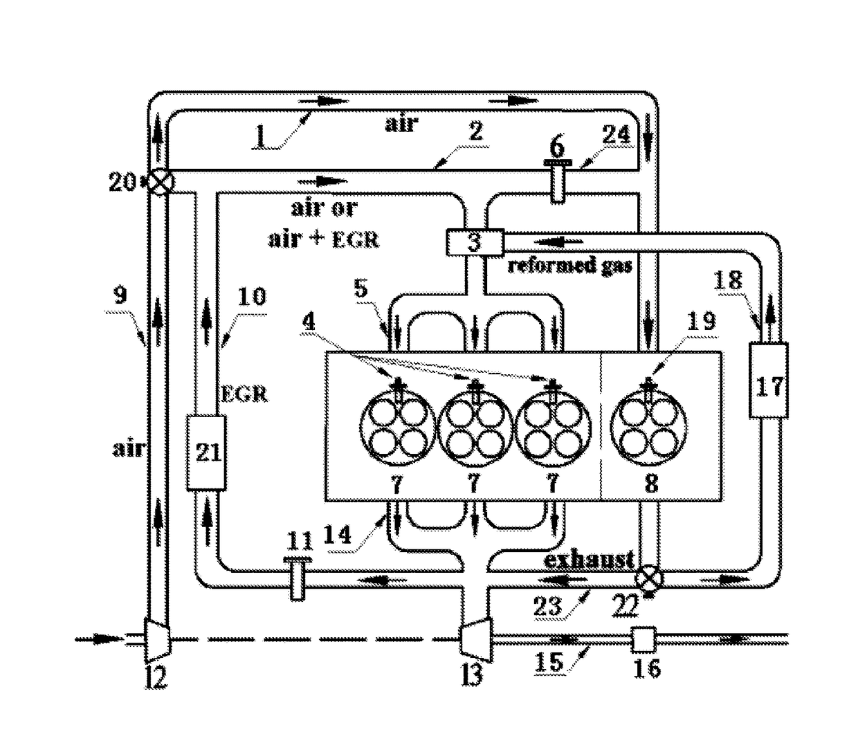
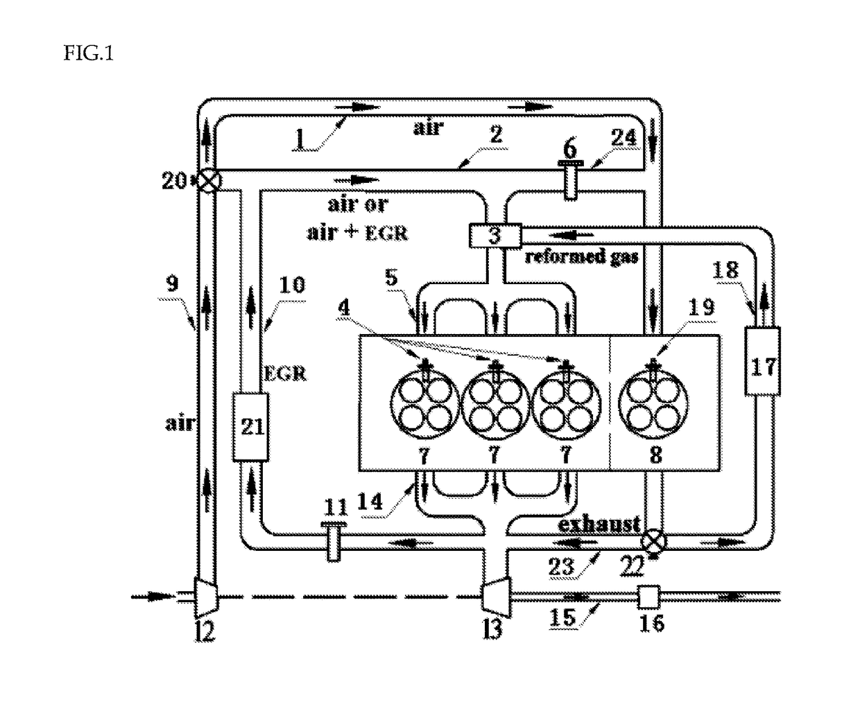
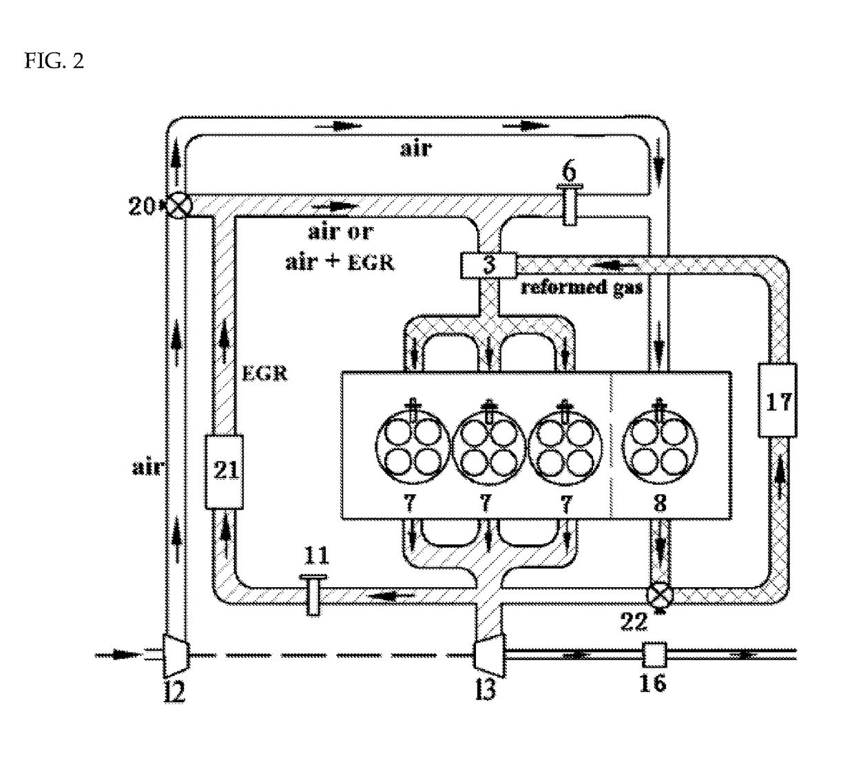
[0048]As shown in FIG. 1, the novel engine controlled by combustion reaction path of the present invention comprises a fuel tank, a fuel supply system, a fuel injection system and an air inlet system, as well as a plurality of working cylinders and at least one fuel reforming cylinder.

[0049]The air inlet system of the engine comprises a turbine 13, a compressor 12, a main air inlet pipe 9 connected to the compressor 12, and a first EOV 20 installed on the main air inlet pipe 9. The main air inlet pipe 9 is divided into two ways by the first EOV 20, one is a working cylinder air inlet pipe 2, and the other is a reforming cylinder air inlet pipe 1.

[0050]A working loop is arranged between the main air inlet pipe 9 and the working cylinder air inlet pi...


PUM


Abstract

The present invention discloses a novel engine controlled by combustion reaction path, which cylinders comprise working cylinders and reforming cylinders. According to the operational condition of engine, the engine is used for compressing, heating and reforming the fuel injected from the reforming cylinder injector; by controlling the reaction boundary conditions between fuel and air, the reforming cylinder can exhaust partial intermediate products or oxidation products of the different oxidation stages; the products are then mixes with the inlet air in the pre-mixing chamber and then is introduced into the working cylinder. Under operating in different working conditions, the engine can discharge the mixed gas with different activities under different oxidation stages by regulating the corresponding boundary conditions of the reforming reaction of the reforming cylinder, and can achieve concentration stratification and activity stratification of the mixed gas in the working cylinder by using the fuel injected from the working cylinder injectors, and can effectively achieve high effectiveness and broaden the scope of clean combustion by changing the combustion reaction path. The present invention just adopts simple oxidation reaction post-treatment device, and then the emission of the engine can meet the requirement of EuroVI emission regulation.

Description

CROSS REFERENCE TO RELATED APPLICATIONS[0001]This is a continuation-in-part application (CIP) of International Application No. PCT / CN2015 / 095477, filed Nov. 25, 2015, which claims priority from a Chinese Patent Application No. CN201510512821.8, filed Aug. 19, 2015.FIELD OF THE INVENTION[0002]The present invention relates to a novel combustion concept and device involving an engine regulated by combustion reaction path, more particularly to a system utilizing a plurality of cylinders of an engine as fuel reforming cylinders and others as working cylinders, and introducing the oxidation products with various reactivities generated in different oxidation stages into the working cylinders according to different working conditions.BACKGROUND OF THE INVENTION[0003]So far, the internal combustion engine is still the existing power plant with highest thermal efficiency, largest unit volume and mass power, and is widely utilized in the worldwide. However, as the energy shortage and environme...

Claims


Application Information

Patent Timeline
Patent Type & Authority Applications(United States)
IPC IPC(8): F02M26/04F02M26/22F02M26/51F02M26/53F02B37/00F02B47/10
CPCF02M26/04F02B37/00F02M26/22F02M26/51F02M26/53F02B47/10F02B47/08F02M26/05F02M26/43Y02T10/12
Inventor YAO, MINGFAWANG, YANGJIA, GUORUIWANG, HUWEI, LIXIA
Owner TIANJIN UNIV
Learn More