Method and apparatus for generating a three dimensional image

a three-dimensional image and image processing technology, applied in the field of three-dimensional image processing, can solve the problems of high computational resource consumption, computational complexity, and potential image degradation, and achieve the effects of reducing cross-talk effects, improving perceived image quality, and reducing the perceptual impact of image degradation and artifacts

Active Publication Date: 2017-05-25
KONINKLJIJKE PHILIPS NV
View PDF2 Cites 13 Cited by
  • Summary
  • Abstract
  • Description
  • Claims
  • Application Information

AI Technical Summary

Benefits of technology

[0025]The invention may in many embodiments provide an improved three dimensional image which when displayed on a three dimensional display, such as an autostereoscopic display, may provide improved perceived image quality. In many embodiments, the approach may result in e.g. perceived reduced cross-talk effects, e.g. when the second three dimensional image is presented on an autostereoscopic display. The approach may in many embodiments generate a three dimensional image in which the perceptual impact of image degradations and artifacts is reduced. When displayed, a viewer may perceive a more natural looking three dimensional scene. The approach may in particular in many embodiments provide a smoother experience when a user moves through the view cones of an autostereoscopic display.
[0026]The invention may in many embodiments reduce complexity. The approach may in many scenarios substantially reduce the required amount of three dimensional processing of image data. The approach may in many embodiments provide a more efficient use of available computational resource, or may e.g. reduce the required computational resource. Reduced complexity processing can be achieved for large areas of the output three dimensional image. The computational resource usage may be reduced substantially. The approach may for example enable generation of a relatively high number of view images even in devices with relatively low computational capability.
[0027]The invention may in many embodiments and scenarios provide an improved computational resource versus image quality trade-off, In particular, the approach may allow the available computational resource to be targeted at the most critical parts of the three dimensional image. Thus, the adaptation of the number of views represented by image blocks generated by the first image generating unit based on a property of the three dimensional image may adapt the available processing power to improve image quality where it is most likely to be noticeable by a user. Specifically, it may allow artefact reduction and mitigation to be focused on areas where such artefacts are most likely to occur or to be most noticeable.

Problems solved by technology

However, as this is relatively inconvenient to the user, it is in many scenarios desirable to use autostereoscopic displays that directly generate different views and projects them to the eyes of the user.
However, the representation of different views provides additional complications and potential image degradations.
However, a disadvantage of such an approach is that it is very computationally demanding and requires a high computational resource.
However, although such an approach may reduce the overall computational resource usage, it also tends to introduce a number of disadvantages.
In particular, the approach tends to reduce the perceived image quality and introduces a number of artefacts.
Also, if a user moves relative to the display such that the eyes of the viewer move through multiple views of the view cone, a relatively uneven experience will result where image objects may appear to jump or jitter in position as the viewer's eyes move between the views.
However, this increases complexity and resource use, and thus there is an inherent trade-off between quality and complexity which tends to be suboptimal in prior art systems.

Method used


Image

  • Method and apparatus for generating a three dimensional image
  • Method and apparatus for generating a three dimensional image
  • Method and apparatus for generating a three dimensional image

Examples


Embodiment Construction

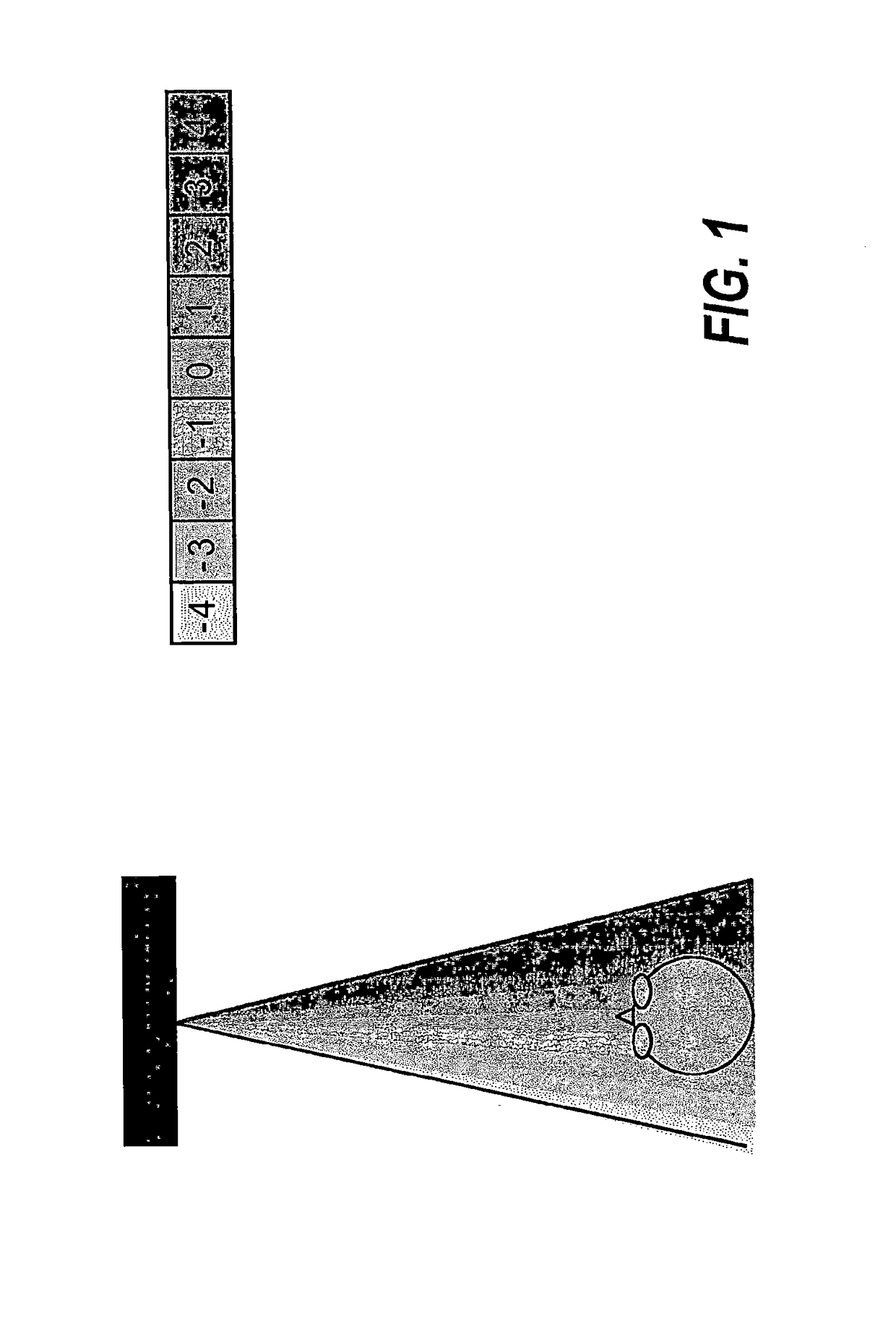
[0100]The following description focuses on embodiments of the invention applicable to an autostereoscopic display used to display three dimensional images. However, it will be appreciated that the invention is not limited to this application but may be applied to many other applications, including for example stereoscopic displays based on view separating glasses.

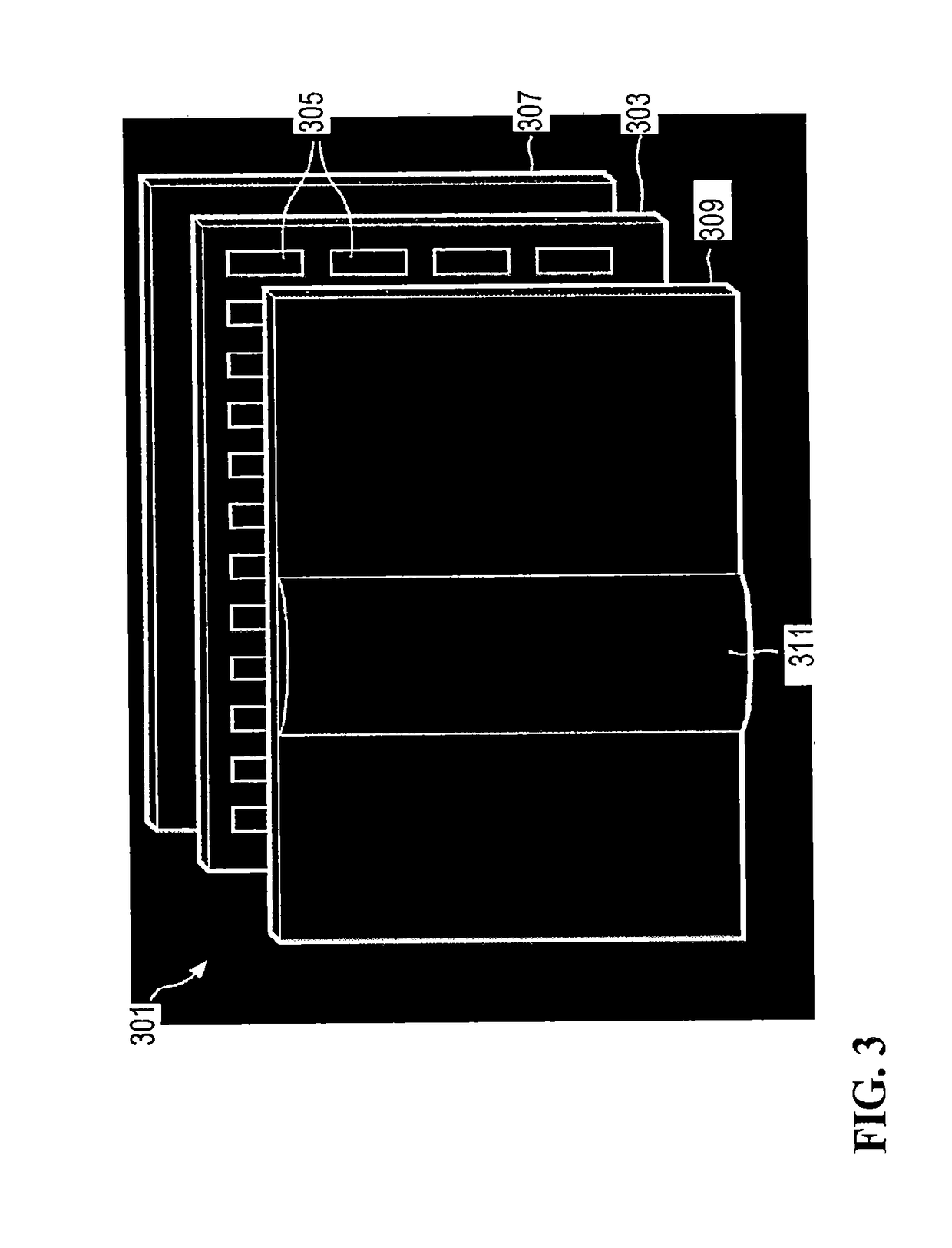
[0101]The autostereoscopic display arrangement 301 comprises a display panel 303. The display arrangement 301 may contain a light source 307, e.g., when the display is an LCD type display, but this is not necessary, e.g., for OLED type displays.

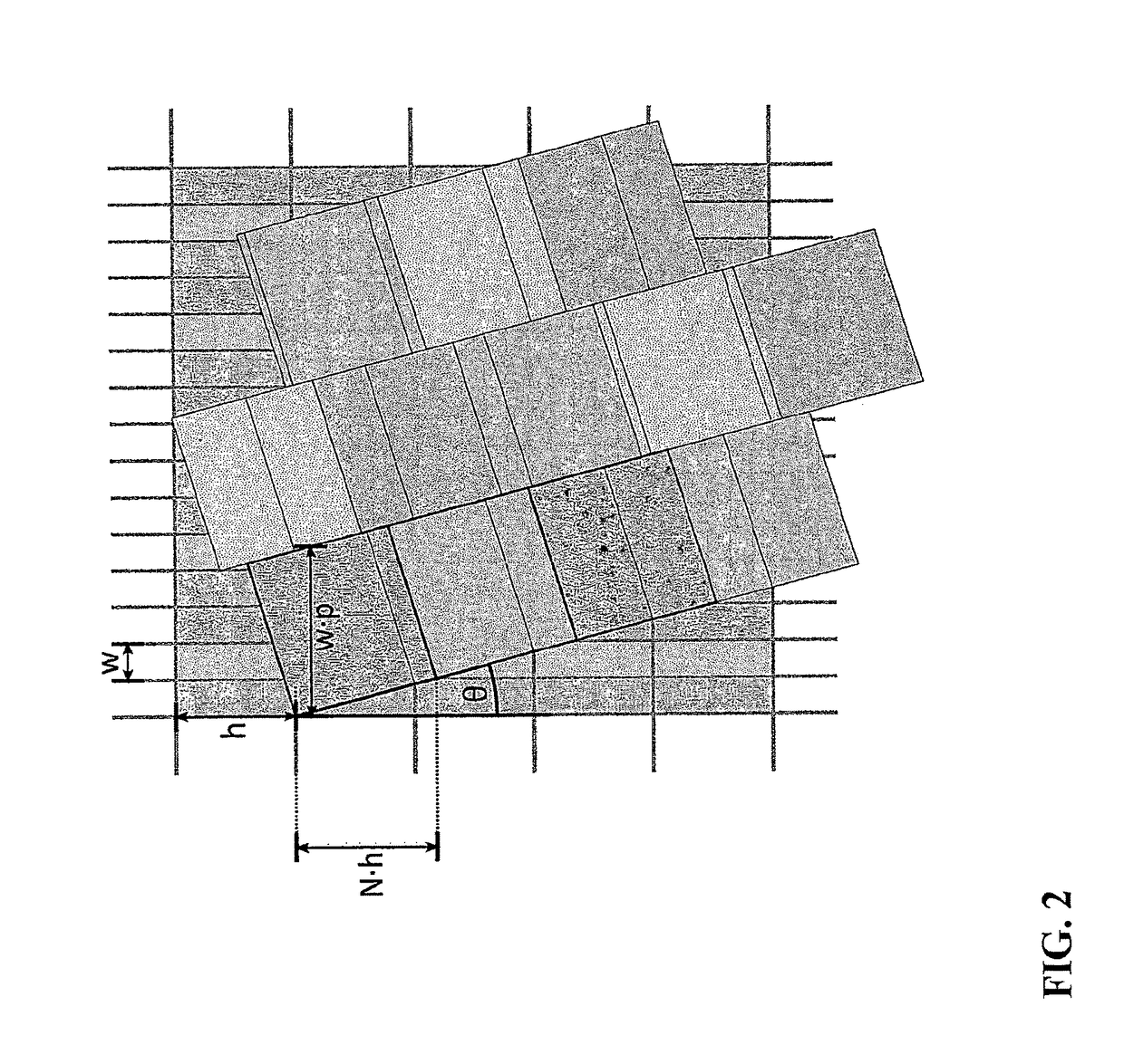
[0102]The display arrangement 301 also comprises a view forming optical element 309 in the form of a lenticular sheet, arranged over the display side of the display panel 303, which performs a view forming function. The view forming optical element 309 comprises a row of lenticular lenses 311 extending parallel to one another, of which only one is shown with exaggerated dimensions fo...


PUM


Abstract

An autostereoscopic 3D display comprises a first unit (503) for generating an intermediate 3D image. The intermediate 3D image comprises a plurality of regions and the first unit (503) is arranged to generate a first number of image blocks of pixel values corresponding to different view directions for the region regions. The number of image blocks is different for some regions of the plurality of regions. A second unit (505) generates an output 3D image comprising a number of view images from the intermediate 3D image, where each of the view images correspond to a view direction. The display further comprises a display arrangement (301) and a driver (507) for driving the display arrangement (301) to display the output 3D image. An adaptor (509) is arranged to adapt the number of image blocks for a first region in response to a property of the intermediate 3D image or a representation of a three dimensional scene from which the first image generating unit (503) is arranged to generate the intermediate image.

Description

FIELD OF THE INVENTION[0001]The invention relates to processing of a three dimensional image, and in particular, but not exclusively, to generation of a three dimensional image for presentation on an autostereoscopic display.BACKGROUND OF THE INVENTION[0002]Three dimensional (3D) displays are receiving increasing interest, and significant research in how to provide three dimensional perception to a viewer is being undertaken. 3D displays add a third dimension to the viewing experience by providing a viewer's two eyes with different views of the scene being watched. This can be achieved by having the user wear glasses to separate two views that are displayed. However, as this is relatively inconvenient to the user, it is in many scenarios desirable to use autostereoscopic displays that directly generate different views and projects them to the eyes of the user. Indeed, for some time, various companies have actively been developing autostereoscopic displays suitable for rendering thre...

Claims


Application Information

Patent Timeline
Patent Type & Authority Applications(United States)
IPC IPC(8): H04N13/00H04N13/04
CPCH04N13/0011H04N13/0402H04N13/0022H04N2213/003H04N13/0497H04N13/0447H04N2213/001H04N13/0422H04N13/305H04N13/275H04N13/282H04N13/111H04N13/128H04N13/302H04N13/324H04N13/351H04N13/398G06T15/20H04N13/00
Inventor VANDEWALLE, PATRICK LUC ELSKROON, BARTVAREKAMP, CHRISTIAAN
Owner KONINKLJIJKE PHILIPS NV
Why Eureka
Try Eureka