AI technical title is built by Patsnap AI team. It summarizes the technical point description of the patent document.
a technology of connecting parts and humidifiers, applied in the direction of respirators, instruments, heat measurement, etc., can solve the problems of uncontrollable condensation or “rainout”, significant heat loss to ambient cooling, etc., and achieve the effect of reducing the likelihood of liquid spillag
Active Publication Date: 2017-06-01
FISHER & PAYKEL HEALTHCARE LTD
View PDF5 Cites 26 Cited by
Summary
Abstract
Description
Claims
Application Information
AI Technical Summary
This helps you quickly interpret patents by identifying the three key elements:
Problems solved by technology
Method used
Benefits of technology
Benefits of technology
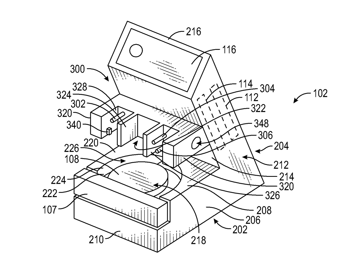
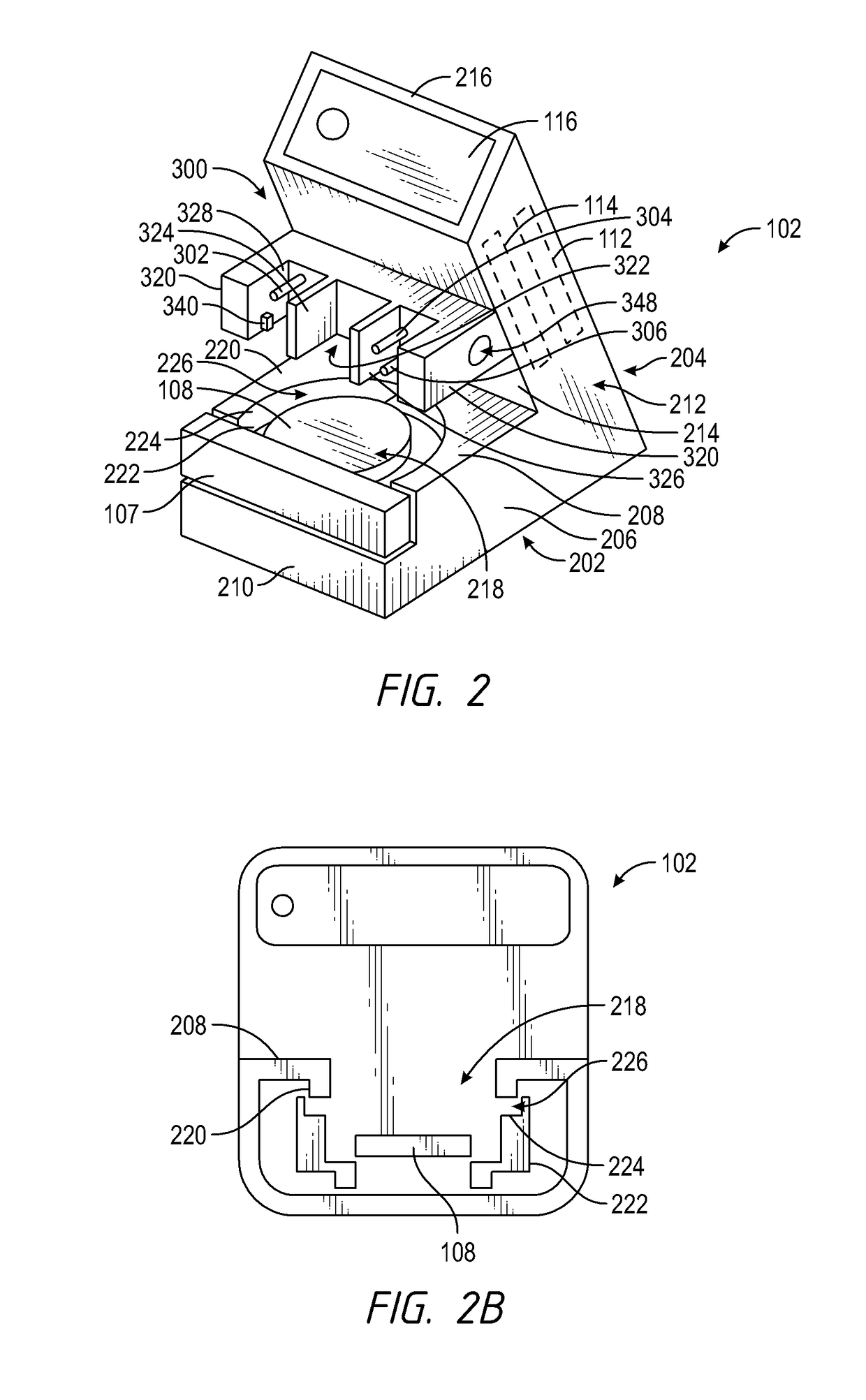
The patent text describes a humidification system with a base unit and cartridges. The system includes sensor probes that are positioned to improve accuracy and reduce wall effects. The cartridges have calibration data stored on a data storage component for calibrating the sensors. The system also has a releasable and lockable connection between the cartridges and the outlet of the humidification chamber to ensure correct orientation and prevent unwanted rotation. The base unit has an inlet and an outlet port with a sensor probe positioned to make direct contact with the inlet. The system also includes a shroud to protect the sensors and prevent spilled liquid from coming into contact with the electrical connector. The technical effects of the system include improved accuracy of the sensors, reduced heat contamination, and prevention of damage and rotation during assembly and use.
Problems solved by technology
Unheated tubing allows significant heat loss to ambient cooling.
This cooling may result in unwanted condensation or “rainout” along the length of the tubing transporting warm, humidified air.
Method used
Image
Click on the blue label to locate the original text in one second.
Reading with bidirectional positioning of images and text.
Examples
Embodiment Construction
[0148]Certain embodiments and examples of humidification systems are described herein. Those of skill in the art will appreciate that the disclosure extends beyond the specifically disclosed embodiments and / or uses and obvious modifications and equivalents thereof. Thus, it is intended that the scope of the disclosure should not be limited by any particular embodiments described herein.
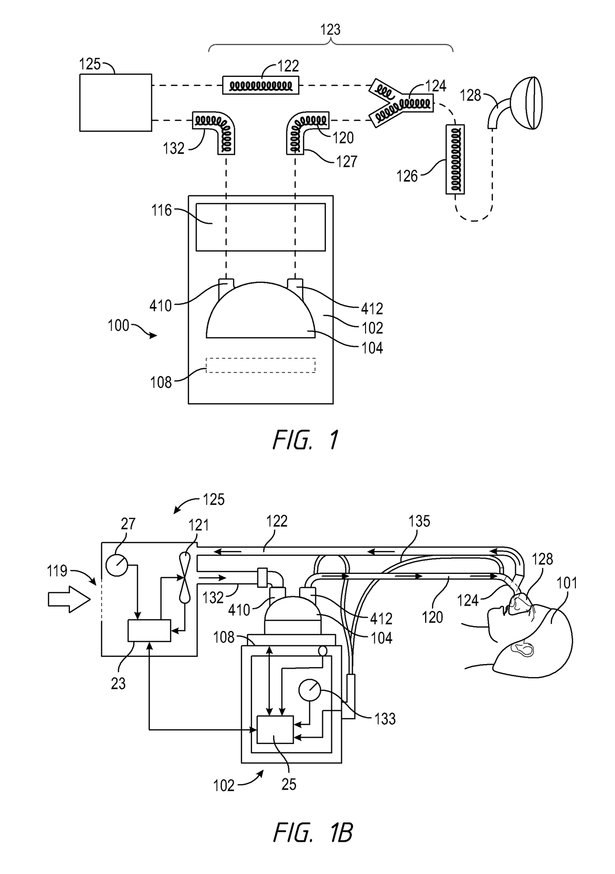
[0149]FIGS. 1A and 1B schematically illustrate example embodiments of a humidification system 100 that, in some applications, can be used with breathing therapies, positive pressure apparatus, noninvasive ventilation, surgical procedures including but not limited to laparoscopy, and the like. Desirably, the humidification system 100 can be adapted to supply humidity or vapor to a supply of gases. The humidification system 100 can be used with continuous, variable, or bi-level positive airway pressure (PAP) systems or other form of respiratory therapy. In some configurations, the h...
PUM
Abstract
A humidification system can include a heater base, a humidification chamber, and a breathing circuit. A cartridge can be removably coupled to the heater base. The cartridge can include various sensors, probes, sensor wire connectors, heater wire connectors, and / or other features. The cartridge can include features configured to mate with corresponding features on the humidification chamber and the heater base. The cartridge includes a memory, such as an EEPROM, or other suitable storage device. When the cartridge is installed on the heater base, the memory is electrically connected to a processor and / or memory of the heater base. Various models of cartridges can be produced for use with different humidification chambers, breathing circuits, and / or therapies. A connector can be configured to couple an inspiratory conduit to an outlet port of the humidification chamber. The connector can provide a pneumatic connection to the outlet port and an electrical connection to the cartridge.
Description
INCORPORATION BY REFERENCE[0001]Any and all applications for which a foreign or domestic priority claim is identified in the Application Data Sheet as filed with the present application are hereby incorporated by reference under 37 CFR 1.57.[0002]The present application claims priority benefit of U.S. Provisional Application No. 61 / 877,784, filed on Sep. 13, 2013; U.S. Provisional Application No. 62 / 024,969, filed on Jul. 15, 2014; U.S. Provisional Application No. 61 / 919,485, filed on Dec. 20, 2013; U.S. Provisional Application No. 61 / 877,566, filed on Sep. 13, 2013; U.S. Provisional Application No. 62 / 032,462, filed on Aug. 1, 2014; U.S. Provisional Application No. 61 / 877,622, filed on Sep. 13, 2013; and U.S. Provisional Application No. 61 / 877,736, filed on Sep. 13, 2013, each of which is hereby incorporated by reference in its entirety.BACKGROUND[0003]Field[0004]The present disclosure generally relates to devices and methods for providing heated and / or humidified gases to a user. ...
Claims
Application Information
Patent Timeline
Application Date:The date an application was filed.
Publication Date:The date a patent or application was officially published.
First Publication Date:The earliest publication date of a patent with the same application number.
Issue Date:Publication date of the patent grant document.
PCT Entry Date:The Entry date of PCT National Phase.
Estimated Expiry Date:The statutory expiry date of a patent right according to the Patent Law, and it is the longest term of protection that the patent right can achieve without the termination of the patent right due to other reasons(Term extension factor has been taken into account ).
Invalid Date:Actual expiry date is based on effective date or publication date of legal transaction data of invalid patent.
Patent Type & AuthorityApplications(United States)
InventorOSBORNE, HAMISHMILLAR, GAVIN WALSHEVANS, STEPHEN DAVIDHOLYOAKE, BRUCE GORDONSTANTON, JAMES WILLIAMMCCAULEY, DAVID LEONMCDERMOTT, GARETH THOMASMCKENNA, NICHOLAS JAMES MICHAELNORTON, MYFANWY JANE ANTICAELSWORTH, ADRIAN JOHNANDRESEN, MICHAEL JOHNLAMBERT, JONATHAN ANDREW GEORGEGURM, SANDEEP SINGHPARIS, TESSA HAZELGRIFFITHS, JOSEPH NATHANIELSI, PINGSIMS, CHRISTOPHER GARETHSTOKS, ELMO BENSONCHEUNG, DEXTER CHI LUNSEEKUP, PETER ALANLANG, RICHARD EDWARDTONKIN, PAUL JAMESKWAN, IAN LEE WAI

