Electrolysis system

Inactive Publication Date: 2017-06-01
H2SG ENERGY PTE LTD
View PDF3 Cites 1 Cited by
  • Summary
  • Abstract
  • Description
  • Claims
  • Application Information

AI Technical Summary

Benefits of technology

The patent text explains the efficiency of an electrolysis cell, which increases with temperature. This is because when the temperature is higher, the electrolysis cell generates less heat and can use the heat generated during the process to maintain the system at a higher temperature and provide energy to evaporate water needed for the process. The text also mentions the importance of minimizing heat loss between the humidifier and the electrode gas space by locating the humidifier close to the inlet of the gas space. Additionally, the text explains the optimal velocity for gas flow through the electrode gas space, depending on the operating temperature and pressure of the system. A lower velocity is needed at high temperatures and pressure to ensure efficient heat transfer and sufficient water supply, while a higher velocity is required at lower temperatures and pressure to maintain system efficiency.

Problems solved by technology

(A) A separate thermal exchange portion is required to be attached to the cell introducing additional complexity to the overall system and introducing thermal losses through the connection materials;
(B) High cost and complexity of the cell heat management system that includes thermal sensors and control equipment that provides circulation and maintains temperature of the liquid coolant at various operating conditions; and
(C) Low reliability due to water condensation within the gas recirculation loop.
However, the described system does not have means to maintain substantially constant temperature in the gas recirculation loop.
Water supply is limited by the amount of water leaving the cell.
Thus, such temperature variations can eventually lead to the electrolyte drying out and subsequent failure of the device.

Method used


Image

  • Electrolysis system
  • Electrolysis system
  • Electrolysis system

Examples


Embodiment Construction

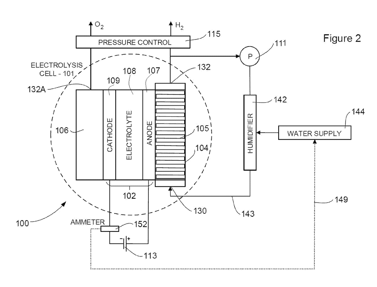
[0045]The present invention provides an electrolysis cell which produced hydrogen and oxygen product gases from a water supply. The electrolysis cell of the present invention generally includes a membrane electrode assembly containing an anode, a cathode and electrolyte therebetween.

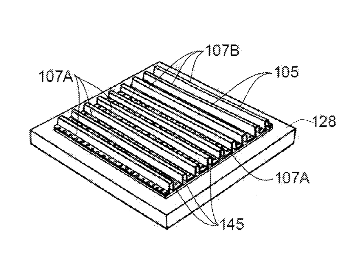
[0046]One development provided by the present invention is the use of a heat transfer arrangement that facilitates efficient heat transfer between the membrane electrode assembly and either the oxygen gas or hydrogen product gas produced by the membrane electrode assembly. The heat transfer arrangement of the present invention is housed in an electrode gas chamber on the non-electrolyte side of the anode or cathode depending on the desired configuration of the electrolysis cell. The heat transfer arrangement is physically connected to the respective anode or cathode. Product oxygen or hydrogen product gas circulates through electrode gas chamber over the heat transfer arrangement to remove heat from the ...


PUM


Abstract

An electrolysis cell system (100) for producing hydrogen and oxygen from water comprising: at least one electrolysis cell (101) including a membrane electrode assembly (102) which comprises at least one pair of gas permeable electrodes (107, 109) comprising an anode (107) and a cathode (109), and an ion conductive electrolyte (108) arranged between each pair of anode (107) and cathode (109); an electrode gas space (104, 106) on the non-electrolyte side of each electrode (107, 109) comprising an anode gas space (104) and a cathode gas space (106), at least one electrode gas space (104) including an inlet (130) and an outlet (132); a recirculating loop (143) for recirculating at least a portion of produced oxygen product gas from the outlet (132) of at least one electrode gas space (104) to the inlet (130) of the respective electrode gas space (104) and through the respective electrode gas space (104); a water supply vessel (142) in fluid communication with the recirculating loop (143), the water supply vessel (142) vaporising water from a water supply (144) utilising heat of vaporisation provided by the respective product gas in the recirculating loop (143) and feeding said water vapour into the recirculating loop (143); and a heat transfer arrangement (105) for transferring heat between the membrane electrode assembly (102) and gas in the anode gas space (104) located in the electrode gas space (104) fluidly connected to the recirculating loop through the inlet and outlet thereof, wherein the heat transfer arrangement (105) is in contact with the membrane electrode assembly (102) and also allows for gas circulation between the membrane electrode assembly (102) and the respective gas space (104).

Description

TECHNICAL FIELD[0001]The invention generally relates to an electrolysis process and apparatus for carrying out said electrolysis process to produce clean gases such as hydrogen and oxygen. The invention is particularly applicable for low temperature gas electrolysis cell systems for electrolysing water and it will be convenient to hereinafter disclose the invention in relation to that exemplary application. However, it is to be appreciated that the invention is not limited to that application and could be used in other electrolysis applications.BACKGROUND OF THE INVENTION[0002]The following discussion of the background to the invention is intended to facilitate an understanding of the invention. However, it should be appreciated that the discussion is not an acknowledgement or admission that any of the material referred to was published, known or part of the common general knowledge as at the priority date of the application.[0003]Low temperature gas electrolysis cell systems have a...

Claims


Application Information

Patent Timeline
IPC IPC(8): C25B15/02C25B9/10C25B15/08C25B1/10C25B9/23
CPCC25B15/02C25B15/08C25B9/10C25B1/10C25B9/00Y02E60/36C25B1/04C25B9/73C25B9/23
Inventor IZGORODIN, IVANIZGORODIN, ALEXEY
Owner H2SG ENERGY PTE LTD
Why Eureka
Try Eureka