
Cleaning method

Inactive Publication Date: 2017-06-01
DISCO CORP
View PDF4 Cites 11 Cited by
  • Summary
  • Abstract
  • Description
  • Claims
  • Application Information

AI Technical Summary

Benefits of technology

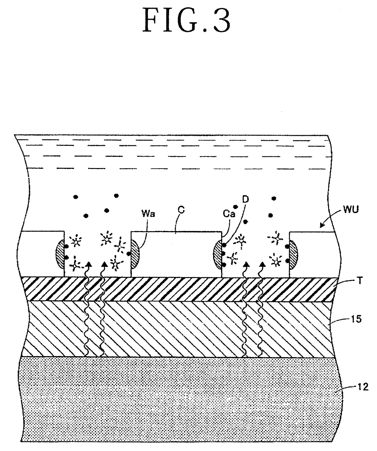
The present invention provides a cleaning method that can prevent modified layer debris from remaining on the sides of chips and reduce the time required to clean them. The method involves immersing the object to be cleaned in a cleaning liquid containing a surface active agent, and filling the spaces between adjacent chips with the cleaning liquid. The application of ultrasonic waves to the cleaning liquid peels off the modified layer debris from the sides of the chips using a synergistic effect of the surface active agent and the ultrasonic cleaning process. This simultaneous cleaning of all the chips reduces the time required to clean them compared to a process where each chip is individually cleaned.

Problems solved by technology

However, the cleaning method disclosed in Japanese Patent Laid-Open No. 2013-105823 is problematic in that the period of time required to clean the chips is long because it is necessary to pick up the divided chips one by one and to apply the cleaning air from the nozzle individually to the chips.

Method used


Image

  • Cleaning method
  • Cleaning method
  • Cleaning method

Examples


Embodiment Construction

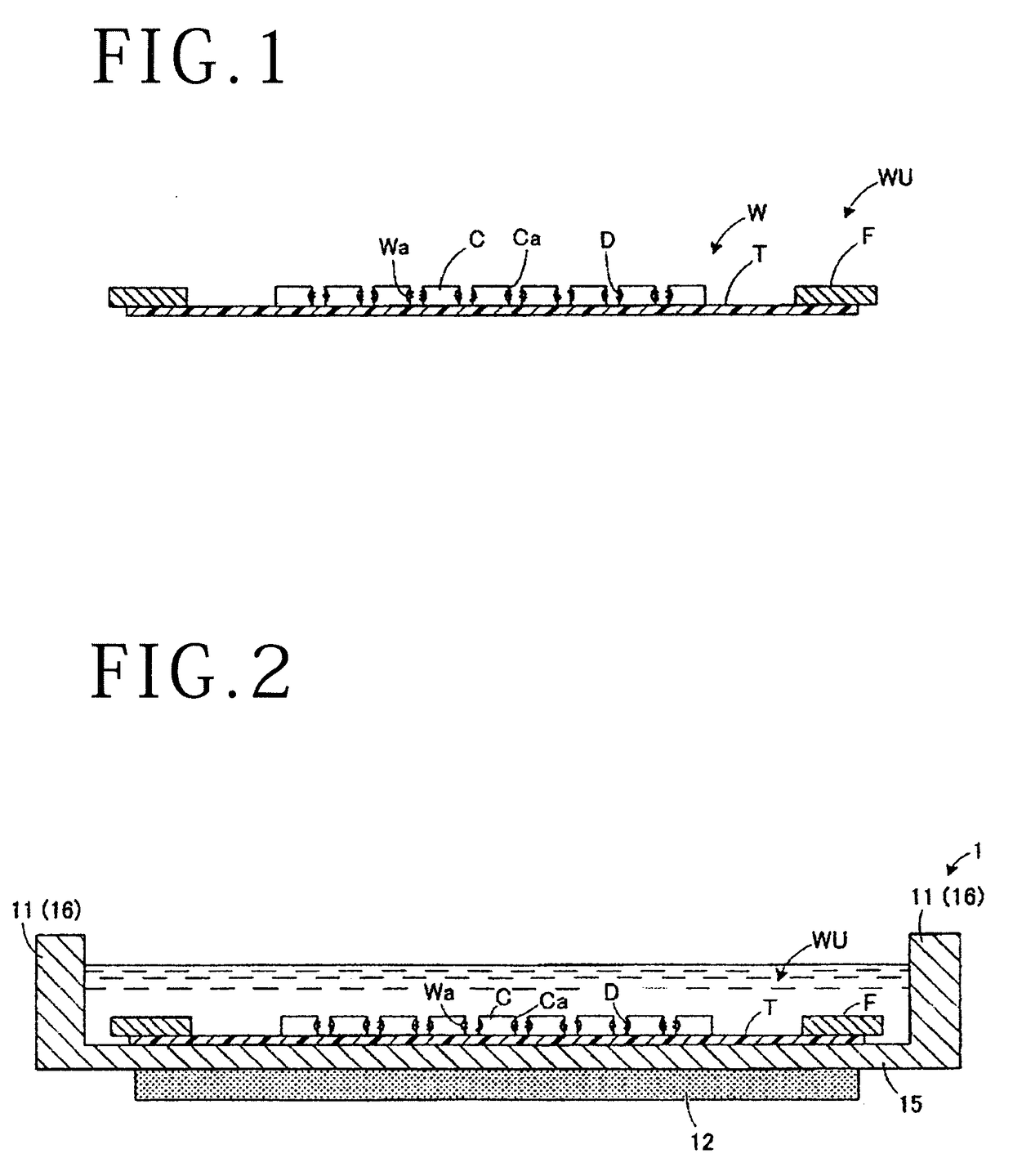
[0019]A cleaning method according to an embodiment of the present invention will be described below with reference to the accompanying drawings. FIG. 1 is a schematic cross-sectional view of an object to be cleaned by the cleaning method according to the embodiment of the present invention. In FIG. 1, the object to be cleaned is illustrated as having a plurality of chips bonded to an adhesive tape serving as a holding member. However, the object to be cleaned may have a plurality of chips bonded to a support board serving as a holding member.

[0020]As shown in FIG. 1, the object to be cleaned includes a wafer W which includes modified layers Wa formed along projected dicing lines by laser beam processing and which is divided into individual chips C, starting from the modified layers Wa. The chips C include the modified layers Wa on side faces Ca thereof, and are bonded to a holding member T such as an adhesive tape or the like with spaces or gaps formed between adjacent ones of the c...


PUM


Abstract

A method of cleaning an object that includes a plurality of chips divided individually, starting from modified layers, and integral with a holding member, includes the steps of placing the object in a cleaning tank filled with a cleaning liquid which contains a surface active agent, and cleaning away modified layer debris on side faces of the chips with ultrasonic waves generated by ultrasonic oscillating means.

Description

BACKGROUND OF THE INVENTION[0001]Field of the Invention[0002]The present invention relates to a cleaning method for cleaning an object after it has been divided into chips.[0003]Description of the Related Art[0004]In recent years, there has been known a method of dividing a workpiece such as a wafer or the like by forming modified layers within the workpiece along projected dicing lines thereon and applying an external force to the workpiece to divide the workpiece into individual chips (see, for example, Japanese Patent No. 3408805). According to the dividing method disclosed in Japanese Patent No. 3408805, a laser beam having a wavelength (e.g., 1064 nm) that permeates the wafer is focused within the wafer to form the modified layers along the projected dicing lines. The external force is then applied to the wafer by breaking or the like to rupture the wafer, starting from the modified layers where the mechanical strength has been made lower.[0005]Modified layer debris (diced debr...

Claims


Application Information

Patent Timeline
IPC IPC(8): H01L21/02H01L21/683H01L21/67B08B3/12B08B3/08
CPCH01L21/02076B08B3/12B08B3/08H01L2221/68327H01L21/67236H01L21/6836H01L21/67057H01L21/78H01L21/67132
Inventor ZHAO, JINYAN
Owner DISCO CORP
Learn More