Electronic Vapour Inhalers

a vapour inhaler and electronic technology, applied in the field of electronic vapour inhalers, can solve the problems of inhalation or production of harmful chemicals such as carbon dioxide and tar, and achieve the effect of not producing or inhaling harmful chemicals

Active Publication Date: 2017-06-08
JT INT SA
View PDF11 Cites 82 Cited by
  • Summary
  • Abstract
  • Description
  • Claims
  • Application Information

AI Technical Summary

Benefits of technology

[0027]The housing may include an air inlet through which air can flow into the chamber and into the shell through the air-permeable material. A plurality of air inlets could be provided. The housing may be fitted with an airflow control mechanism to vary the

Problems solved by technology

Although inhalation of the vapour creates a physical sensation which is similar to conventional smoking, ha

Method used


Image

  • Electronic Vapour Inhalers
  • Electronic Vapour Inhalers
  • Electronic Vapour Inhalers

Examples


Embodiment Construction

[0036]Embodiments of the present disclosure will now be described by way of example only and with reference to the accompanying drawings.

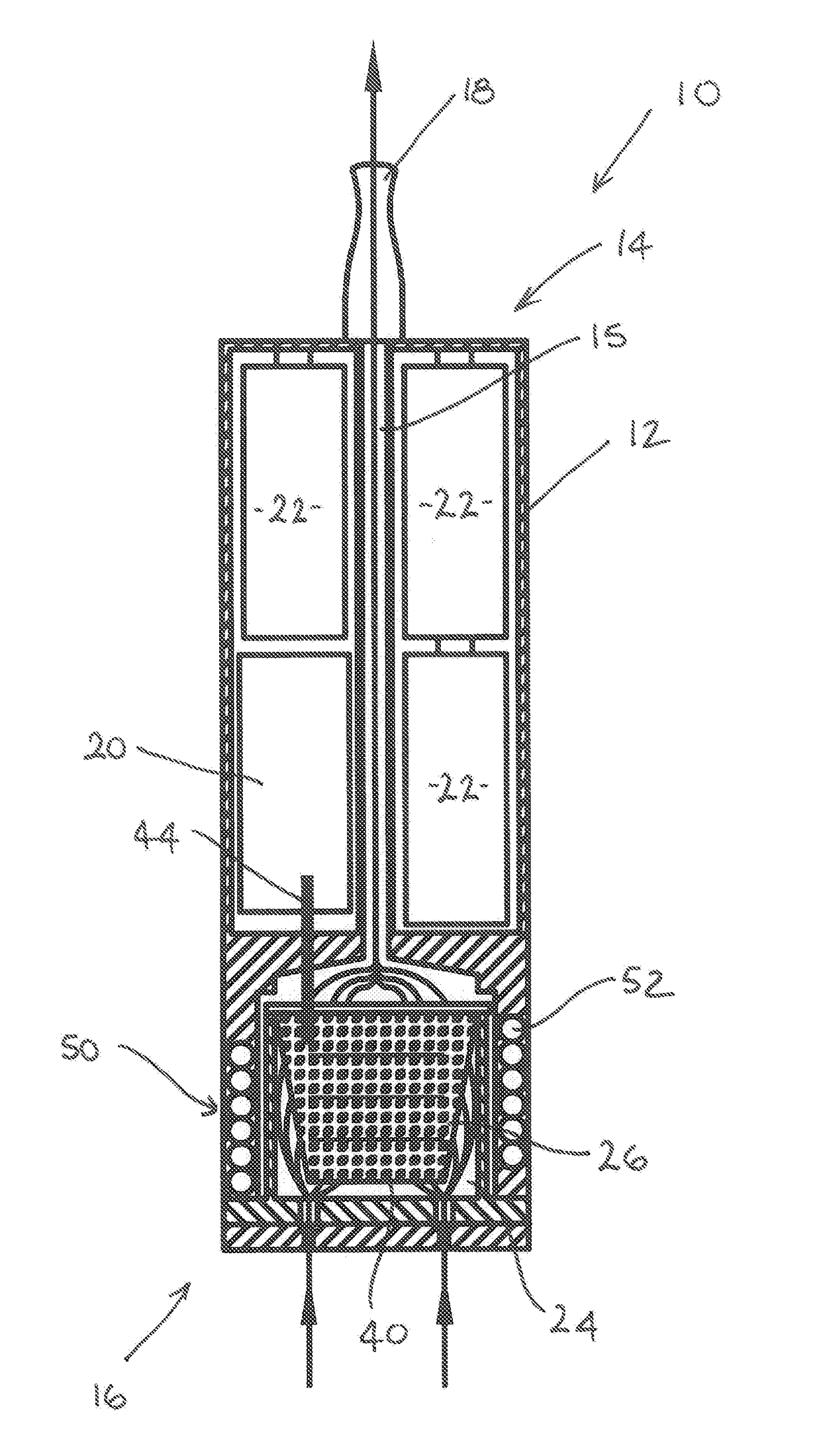
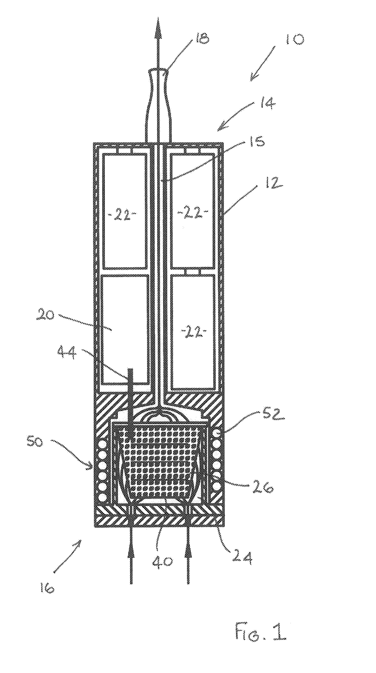
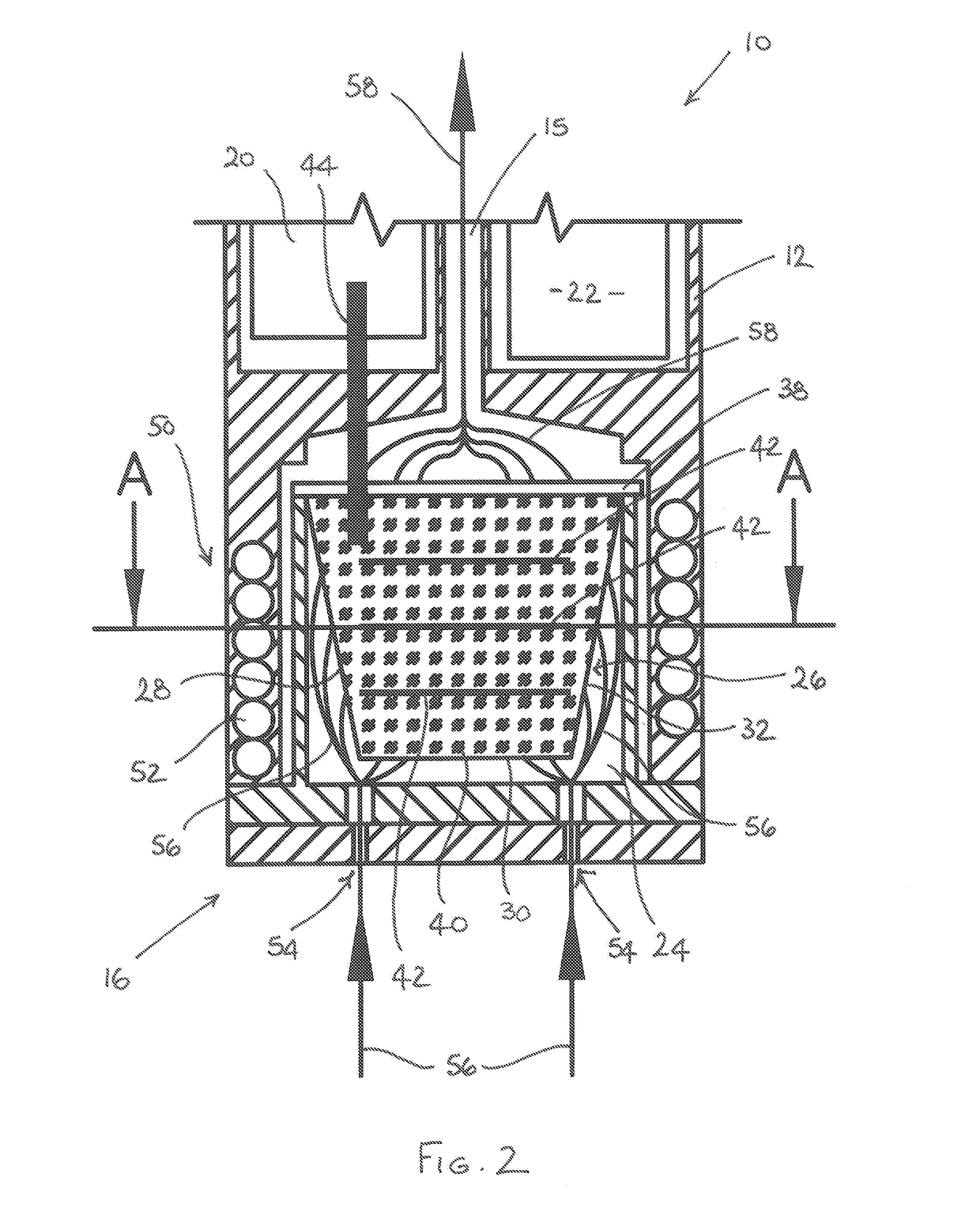
[0037]An electronic vapour inhaler 10 comprises a generally elongate housing 12 having a proximal end 14 and a distal end 16. The electronic vapour inhaler 10 includes a mouthpiece 18 at the proximal end 14 through which a user can inhale vapour generated by heating a flavour-release medium 40. The electronic vapour inhaler 10 includes a control arrangement 20 in the form of a microprocessor (not shown) and a power source 22 in the form of one or more batteries which could, for example, be inductively rechargeable.

[0038]The housing 12 includes a chamber 24 into which a capsule 26 can be removably inserted. In the figures, the chamber 24 is located at the distal end 16 of the housing 12, but this is not strictly necessary and it could be located at any suitable position between the proximal end 14 and the distal end 16. In the illustrated embodiment...


PUM


Abstract

A capsule (26) for an electronic vapour inhaler comprises a shell (28) containing a flavour-release medium (40) and one or more induction heatable elements (42) disposed inside the shell (28) and arranged to heat the flavour-release medium (40) to produce a vapour for inhalation by a user. At least part of the shell (28) is formed of an air permeable material.

Description

TECHNICAL FIELD[0001]The present disclosure relates generally to electronic vapour inhalers and more particularly to a capsule containing a flavour-release medium for use with an electronic vapour inhaler, in which the flavour-release medium can be heated to produce a vapour for inhalation by a user.TECHNICAL BACKGROUND[0002]The use of electronic vapour inhalers (also known as electronic cigarettes, e-cigarettes and personal vaporisers), which can be used as an alternative to conventional smoking articles such as cigarettes, cigars, and pipes, is becoming increasingly popular and widespread. Electronic vapour inhalers, which are usually battery powered, heat and atomise a liquid containing nicotine, to produce a nicotine-containing vapour which can be inhaled by a user. The vapour is inhaled through a mouthpiece to deliver nicotine to the lungs, and vapour exhaled by the user generally mimics the appearance of smoke from a conventional smoking article. Although inhalation of the vap...

Claims


Application Information

Patent Timeline
IPC IPC(8): A24F47/00B65D43/02H05B6/10A24F40/10A24F40/42A24F40/465A24F40/50
CPCA24F47/008B65D43/02H05B6/108A24F40/50A24F40/465A24F40/42A24F40/10A24F47/00A24F40/20A24F40/60A61M15/06A24B15/167A24B15/186A24F40/485H05B6/36A24F40/57A24F40/51A24F7/00
Inventor GILL, MARKVANKO, DANIELBRVENIK, LUBOS
Owner JT INT SA
Why Eureka
Try Eureka