Method and system for controlling robot

a robot and arm technology, applied in the field of method and system for controlling a robot, can solve the problems of reducing the speed of the robot arm's operation, and reducing the work efficiency of the control device, so as to ensure safety, improve work efficiency, and ensure the effect of processing efficiency

Active Publication Date: 2017-06-08
DENSO WAVE INC
View PDF0 Cites 27 Cited by
  • Summary
  • Abstract
  • Description
  • Claims
  • Application Information

AI Technical Summary

Benefits of technology

[0008]It is thus desired to provide a method and system for controlling a robot that are capable of securing the safety of a person when the person approaches the robot and of minimizing the reduction of work efficiency.
[0011]That is, in the case in which the person is detected within the range of the intermediate distance, the operation of the robot main body is paused, the robot main body is operated without deceleration, or the robot main body is operated in a decelerated state depending on whether or not it is possible to acquire the safety skill level of the person or depending on the degree of the acquired safety skill level. Consequently, it is possible both to ensure the safety of the person who is present within the range of the intermediate distance and to prevent the operation of the robot main body from being paused or the robot main body from being operated at a low speed in the same way, thereby minimizing the reduction of work efficiency.
[0018]In the latter case, however, the medium position coordinate value may be acquired. Thereupon, a medium position coordinate value that does not correspond to the acquired person position coordinate value may be acquired on an extension line thereof, as described above. In this state, the person who is closer to the robot main body is in greater danger. Consequently, it may be determined whether or not the safety skill levels of the acquired person position coordinate values of the respective person position coordinate groups are acquired and whether the safety skill levels of the acquired person position coordinate values are high or low. If the operation state of the robot main body is determined by finally evaluating one of the groups having the lowest safety skill level, it is possible to ensure safety through efficient processing.
[0019]In a further preferred system, the control device defines a region in which the robot main body is to operate within a predetermined time from the present time as a monitoring region and defines a region in which the robot arm is not to operate within the predetermined time from the present time as an unmonitored region. In the case in which the measured distance belongs to the intermediate distance and to the unmonitored region, the robot main body is operated without deceleration, since safety is ensured even when a person is present within the range of the intermediate distance. Consequently, it is possible to further improve work efficiency.
[0020]In another further preferred system, the control device operates the robot main body without deceleration even in the case in which the measured distance belongs to the short distance and to the unmonitored region. That is, in the case in which the measured distance belongs to the unmonitored region, the robot body is operated without deceleration, since safety is ensured even when a person is present within the range of the short distance in the same manner as above. Consequently, it is possible to even further improve work efficiency.

Problems solved by technology

In the above case, however, the operation of the robot arm is paused or the speed of operation of the robot arm is reduced every time the person approaches the robot arm, whereby work efficiency is greatly reduced.
Furthermore, in the case in which the distance belongs to the intermediate distance and the safety skill level cannot be acquired, the control device stops the operation of the robot main body.
However, if the laser light is radiated to a person who is present at a position distant from the person who is present at a position close to the laser sensor, the person position coordinate value may not be detected.
In this state, the person who is closer to the robot main body is in greater danger.

Method used


Image

  • Method and system for controlling robot
  • Method and system for controlling robot
  • Method and system for controlling robot

Examples


first embodiment

[0034]Hereinafter, a first embodiment will be described with reference to FIGS. 1 to 8.

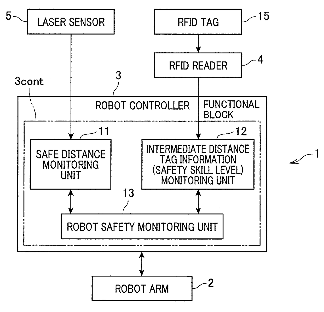
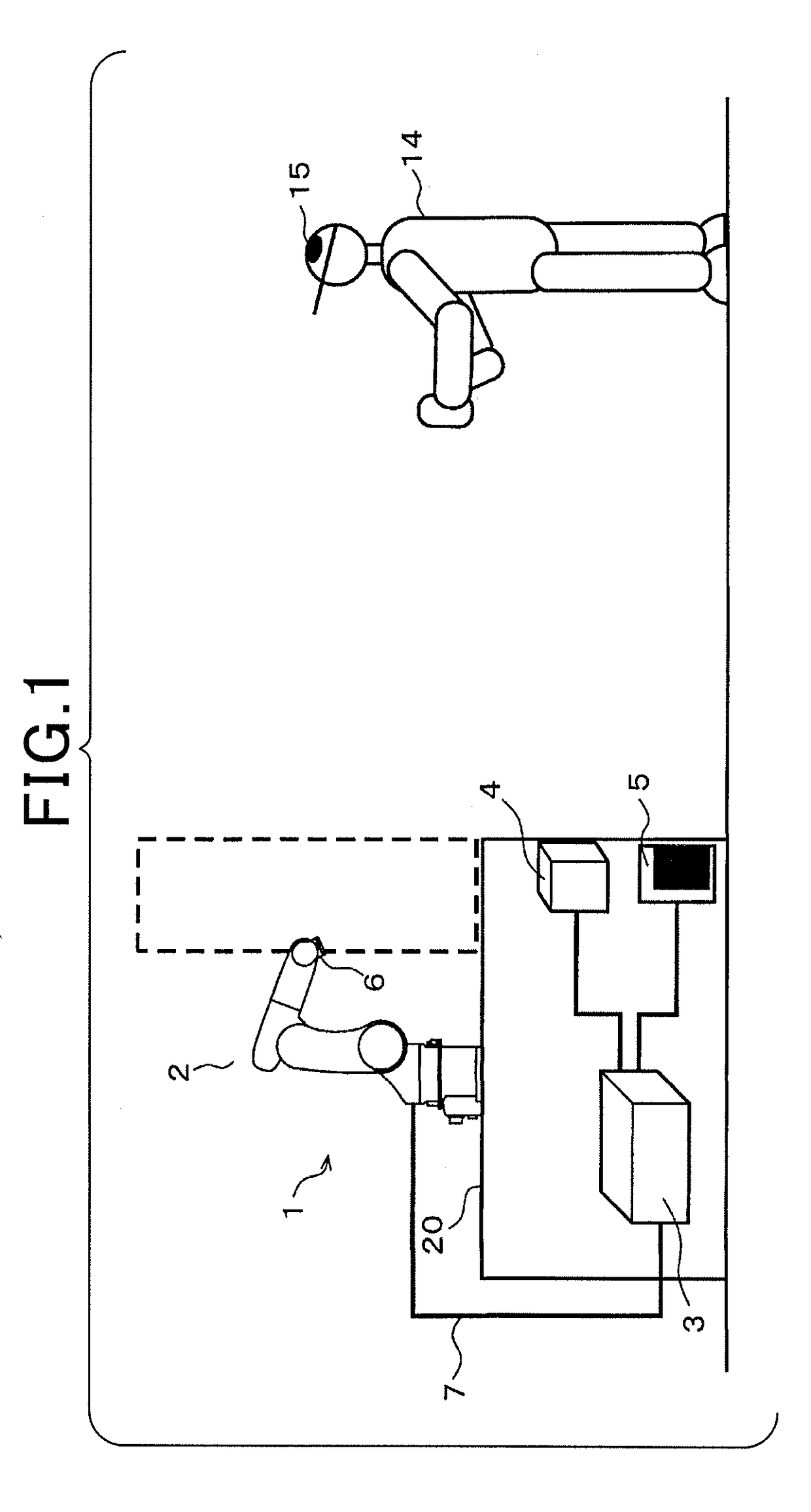
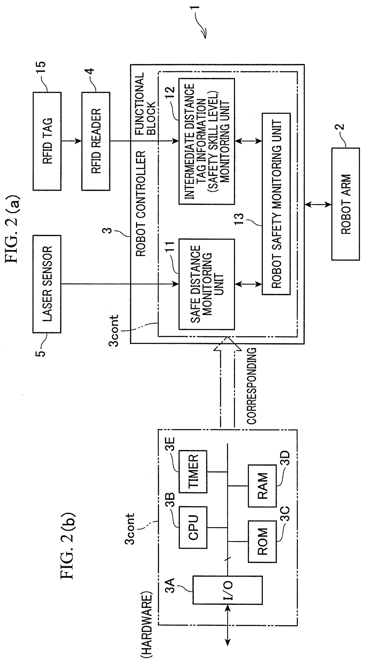
[0035]FIG. 1 is a view schematically showing the external appearance of a robot control system (apparatus) 1 according to this embodiment. The system 1 is an industrial robot. For example, the system 1 includes a robot arm 2 for assembly, a robot controller 3 for controlling the robot arm 2, and an RFID reader 4 and a laser sensor 5 connected to the robot controller 3.

[0036]The robot arm 2, which is a robot main body, is configured as, for example, a 6-axis vertical multi-joint robot. The robot arm 2 is installed on a working stand 20. A detailed description of the general construction of the robot arm 2 will be omitted. The robot arm 2 has six-axis arms, each of which is driven by a servo motor. A hand 6 for holding, for example, a workpiece received in a pallet is provided at the tip of the sixth axis arm. The robot arm 2 is connected to the robot controller 3 via a connection cable 7. The respe...

second embodiment

[0067]The parts of the second embodiment identical to those of the first embodiment are denoted by the same reference symbols, and a description thereof will be omitted. Hereinafter, the parts of the second embodiment different from those of the first embodiment will be described.

[0068]In the second embodiment, as shown in FIG. 9, the movable region of the robot arm 2 is divided into, for example, four regions. The robot arm 2 is operated according to a control program, but the robot safety monitoring unit 13 of the robot controller 3 sets a region that the robot arm 2 is to enter within a predetermined time, for example about 1 second, from a control period at each time as a “monitoring region.” In addition, the robot safety monitoring unit 13 of the robot controller 3 sets a region that the robot arm 2 is not to enter within the predetermined time as a “unmonitored region.”

[0069]As shown in FIG. 10, when the determination result at step S1 is “NO,” the above setting is performed a...

third embodiment

[0071]In the third embodiment, as shown in FIG. 11, step S11 is performed before step S1. Subsequently, at step S12, a person 14 who is present within the range of the short distance in only the “monitoring region” is detected. In the case in which a person 14 is detected within the range of the short distance in the unmonitored region, therefore, the determination result at step S1 is “NO,” and the procedure advances to step S2. Furthermore, the process at step S2 is the same as that of the second embodiment. That is, if the person is present in the unmonitored region, the robot arm 2 does not enter the unmonitored region within a predetermined time even when the person is present within the range of the short distance. Even in this case, therefore, the process is performed in the same manner as the process in the intermediate distance according to the second embodiment.

[0072]According to the third embodiment as described above, the robot controller 3 operates the robot arm 2 at a ...


PUM


Abstract

In a robot control system, the distance from an operating region of a robot arm to a person who is approaching the region is measured using a laser sensor. Information necessary to acquire a safety skill level that is stored in an RFID tag possessed by the person is acquired using an RFID reader. A controller classifies distances into a short distance, which is a distance within the operating region of the arm, a long distance, which is a distance that exceeds a movable region of the arm, and an intermediate distance, which is a distance between the short distance and the long distance. The motion of the arm is controlled by the controller, depending on the distance (i.e., the long distance, the intermediate distance, or the short distance) and the safety level.

Description

CROSS-REFERENCE TO RELATED APPLICATION[0001]This application is based on and claims the benefit of priority from earlier Japanese Patent Application No. 2015-211826 filed on Oct. 28, 2015, the description of which is incorporated herein by reference.BACKGROUND[0002]Technical Field[0003]The present invention relates to a method and system for controlling a robot, and more particularly, to a method and system for controlling the motion of an arm of an industrial robot.[0004]Related Art[0005]In conventional facilities in which robots and people coexist, when a robot controller detects that a person has approached a robot arm using, for example, a light curtain or a laser sensor, control is performed such that the operation of the robot arm is paused or the robot arm is operated at a safe low speed.RELATED ART DOCUMENTPatent Document[0006][Patent Document 1] JP-A 2010-231713[0007]In the above case, however, the operation of the robot arm is paused or the speed of operation of the robot ...

Claims


Application Information

Patent Timeline
Patent Type & Authority Applications(United States)
IPC IPC(8): B25J19/06G05B19/048F16P3/14G08B21/02F16P3/00B25J19/02G05B19/4061
CPCB25J19/06B25J19/022G05B19/048G05B19/4061G05B2219/40202F16P3/003F16P3/14G05B2219/40264G08B21/02B25J9/1676F16P3/144F16P3/147G05B2219/40203
Inventor OGAWA, AKIRA
Owner DENSO WAVE INC
Why Eureka
Try Eureka