Joint seal system having internal barrier and external wings

Active Publication Date: 2017-06-08
SCHUL INT COMPANY
View PDF4 Cites 65 Cited by
  • Summary
  • Abstract
  • Description
  • Claims
  • Application Information

AI Technical Summary

Benefits of technology

[0021]The present invention thus provides redundancy, and potentially a status notification of change

Problems solved by technology

Moreover, these joints are subject to damage over time.
Most damage is from vandalism, wear, and environmental factors, where the seal may become thick and inflexible or are fragile.
These systems, however, often fail due to the differences in compression and expansion of the various constituents, or the lack of bonding between layers, or because the system is directed to a particular purpose, such as water-resistance, but is exposed to fire, causing the seal system to fail and permit water to migrate behind the seal system.
Vandalism, normal wear, and environmental exposure can change or defeat the properties of the exposed surface coating or membrane.
There is also the case where the best material or barrier may not be used because it is aesthetically unpleasing or cannot easily be colored.
Additionally, in some cases the movement of the joint may be limited, sometimes to only twenty-five percent (+/−25%) in compression and expansion, for a total movement of only fifty percent (50%).
Additionally, for pre-compressed joint sealants with a silicone face, a myriad of potential failure risks exists.
Typically, the surface coating of these joints is relatively thin and can be damaged.
Where joint substrate is irregular, a

Method used


Image

  • Joint seal system having internal barrier and external wings
  • Joint seal system having internal barrier and external wings
  • Joint seal system having internal barrier and external wings

Examples


first embodiment

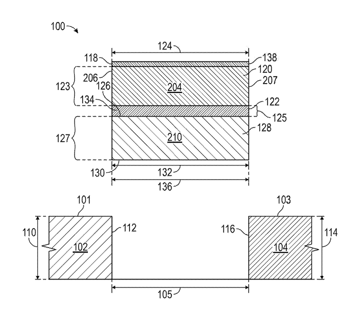
[0070]Referring to FIG. 1, the, joint seal 100 may further include an elastomer 138, such as silicone, adhered to the first body top 118 and / or to the bottom of the bottom-most layer or body 128, the second body bottom 130 in the Alternatively, as illustrated in FIG. 9 the joint seal 100 may alternatively include a resilient flexible surface barrier 902, such as one or more layers of a synthetic rubber roofing membrane, including ethylene propylene diene terpolymer (EPDM), bonded or adhered to the first body top 118, such as by heating of materials or by adhesive. The surface barrier 902 may include at its distant end 904 an upper elongate appendage 906 and, below and generally coplanar, a lower elongate appendage 908, formed, for example, by the lack of adhesive between two adjacent layers or bodies and by cutting a single layer or body along its edge 910. The surface barrier 902 may lap over or about the membrane of a roofing system to provide an effective seal. The surface barri...

embodiment 400

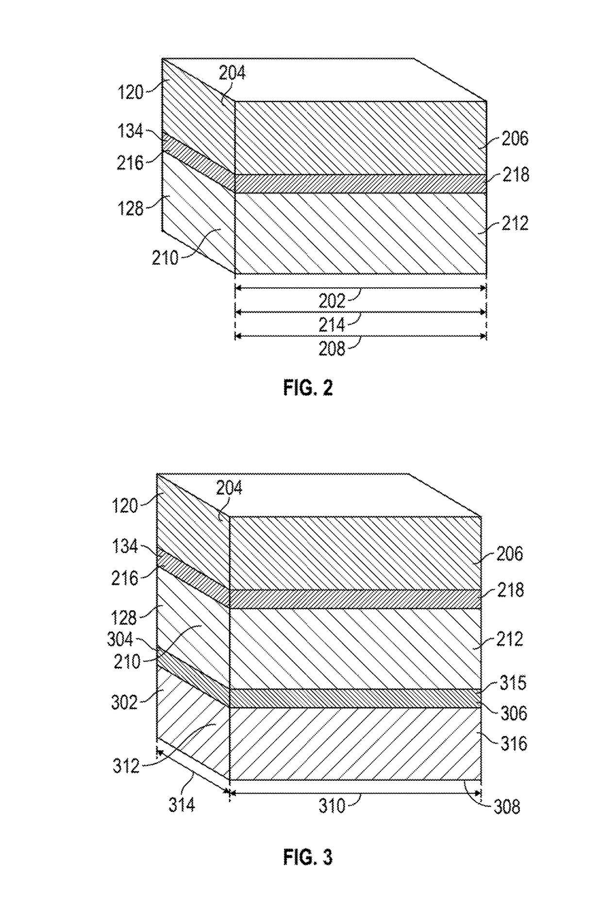
[0078]Referring now to FIG. 10, the barrier 134 of the embodiment of FIG. 3 may be provided with a barrier width 1002 which is greater than the first body width 124 and the second body width 132 to provide a first wing 1006 and a second wing 1008. The second barrier 304 may have a second barrier width 1004, greater than each of the second body width 132 and the third body width 314. Each wing 1006, 1008 may include at its distant end 1010, 1012 an upper elongate appendage 1014, 1016 and, essentially co-planar and below, a lower elongate appendage 1018, 1020, formed, for example, by the lack of adhesive between two adjacent layers or bodies and by cutting a single layer along an edge 1022. Such appendages may lap over or about a roofing system to provide an effective seal, Referring now to FIG. 4, in an alternative embodiment 400, the joint seal includes a first body of compressible foam 120, a second body of compressible foam 128, and a barrier 134 adhered to both the first body of ...

embodiment 500

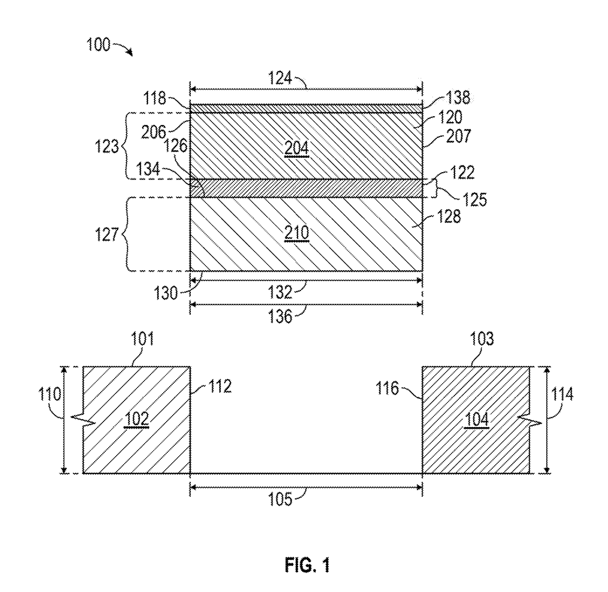
[0081]Referring now to FIG. 5, a further alternative embodiment 500 of the joint seal 100 is illustrated. In the further alternative embodiment 500, the barrier 134 protrudes beyond an end of the joint seal 100, beyond the first body first end 204, providing a tab 502. The barrier 134 may have a resilient flexible barrier length 214 equivalent, i.e. substantially the same, to the first body length 202. The barrier 134 may not be adhered to either the first body of compressible foam 120 or to the second body of compressible foam 128 and an opposing end, or potentially at both ends of the joint seal 100, providing a separable gap 504. As a result, the tab 502 of one unit of the joint seal 100 may be inserted into the end of an adjacent joint seal 100 in the separable gap 504. The length of the tab 502 and the distance of separable gap 504 may be as much, or even more than, two inches. For example, a sixty (60) inch length of joint seal 500 may include a three (3) inch tab 502 and a ma...


PUM

PropertyMeasurementUnit
Thicknessaaaaaaaaaa
Electrical conductivityaaaaaaaaaa
Lengthaaaaaaaaaa

Abstract

An integral multilayer joint seal. Layers of foam, layered co-planar to the adjacent surface, are interspersed with a barrier layer which extends beyond the foam layers to provide a protective surface, a surface for attachment atop adjacent substrates, or a connecting tab for use with adjacent joint seals. The foam layers may be uncompressed or partially compressed at the time of joint formation and may be composed of open or closed, or hybrid, cell foam. The foam may be impregnated with a fire retardant or lay be composed of a fire retardant material, if desired. The barrier may have a tensile strength greater than the adjacent foam. The joint seal may have an elastomer, such as silicone, at its top and/or bottom, and may even include an elastomer layer within or about the barrier.

Description

CROSS-REFERENCE TO RELATED APPLICATIONS[0001]This application is a continuation-in-part of U.S. patent application Ser. No. 15 / 189,671 for Joint seal system, filed Jun. 22, 2016, which is a continuation of U.S. patent application Ser. No. 14 / 630,125, Joint seal system filed Feb. 24, 2015, issued as U.S. Pat. No. 9,404,581 on Aug. 2, 2015 which is incorporated herein by reference, and claims the priority of U.S. Provisional Patent Application No. 61 / 946,311, filed Feb. 28, 2014 for “Joint Seal System,” which is incorporated herein by reference.STATEMENT REGARDING FEDERALLY SPONSORED RESEARCH OR DEVELOPMENT[0002]Not Applicable.BACKGROUND[0003]Field[0004]The present disclosure relates generally to systems for creating a durable seal between adjacent panels, including those which may be subject to temperature expansion and contraction or mechanical shear. More particularly, the present disclosure is directed to providing an integral multilayer joint seal system against one or more of wa...

Claims


Application Information

Patent Timeline
IPC IPC(8): F16J15/06B32B5/18B32B7/12F16J15/10B32B7/022
CPCF16J15/065F16J15/104B32B5/18B32B7/12B32B2307/3065B32B2307/302B32B2581/00B32B2307/304B32B2307/7265B32B2307/7246B32B2307/202B32B2419/00B32B15/046B32B15/20B32B25/045B32B25/14B32B3/02B32B3/04B32B3/30B32B2260/02B32B2260/04B32B2260/046B32B2264/108B32B2266/06B32B2266/08B32B2307/102B32B2307/40B32B2307/54B32B2307/546B32B2307/71B32B2307/7242B32B2307/7244B32B2419/06F16J15/022B32B7/022
Inventor ROBINSON, STEVEN R.
Owner SCHUL INT COMPANY
Why Eureka
Try Eureka