Flexure-based system for measuring torque on a shaft

a technology of flexure and torque, which is applied in the direction of magnetic measurement, measurement devices, instruments, etc., can solve the problems of high cost of mass production market devices and expensive implementation, and achieve the effects of reducing the stress of flexure, preventing overloading of flexure beams, and increasing the amount of flux presen

Inactive Publication Date: 2017-06-08
ROOPNARINE
View PDF0 Cites 0 Cited by
  • Summary
  • Abstract
  • Description
  • Claims
  • Application Information

AI Technical Summary

Benefits of technology

[0004]The invention is a sensor that provides a means of measuring the torque and speed of a rotating shaft. The sensor has a first or input side and a second or output side; each side is coupled, inline, to the shaft of interest. Rotationally coupling the input and output sections of the sensor is a flexure arrangement. At least one pair of permanent magnets is attached to one end of the flexures. The flexures permit the transmission of force and therefore torque from the first (input) section to the second (output) section and vice-versa. The flexures are effectively cantilever beams that are appropriately sized for the torque to be transmitted and for low stresses and they also act as springs that maintain contact with the mating parts of the first (input) section. Hard stops may be used to prevent over loading the flexure beams. The beams may be a composite of a suitably flexible non-magnetic material to which a magnetically soft material is attached or abuts such that the assembly deflects as either one piece or such that deflections of the former produces a predictable deflection of the latter. The obvious preference is for the flexure to be of a unitary construction from a magnetic or ferromagnetic material. To further reduce stress on the flexures, an arrangement in which there are multiple paired but independent flexure beams axially spaced or offset from each other, is also possible. Depending on the strength of magnets used in the system, the additional flexures may or may not have permanent magnets attached to them. Specifically, with lower energy magnets (e.g., Alnico or Ceramic), additional magnets may be used in order to increase the amount of flux present in the magnetic circuit.

Problems solved by technology

There is, therefore, need for a device that can provide these measurements without contacting the shaft as these are often not very reliable, may be expensive to implement and necessarily require the use of a slip ring or twist capsule to obtain an output electronic signal for processing.
However, each of the referenced patents utilize complex magnetic material formulations, either as permanent magnets or as members that must exhibit magnetostriction, in order to achieve the desired data.
Furthermore, complex manufacturing and / or assembly processes render these devices costly for use in mass production markets.

Method used


Image

  • Flexure-based system for measuring torque on a shaft
  • Flexure-based system for measuring torque on a shaft
  • Flexure-based system for measuring torque on a shaft

Examples


Embodiment Construction

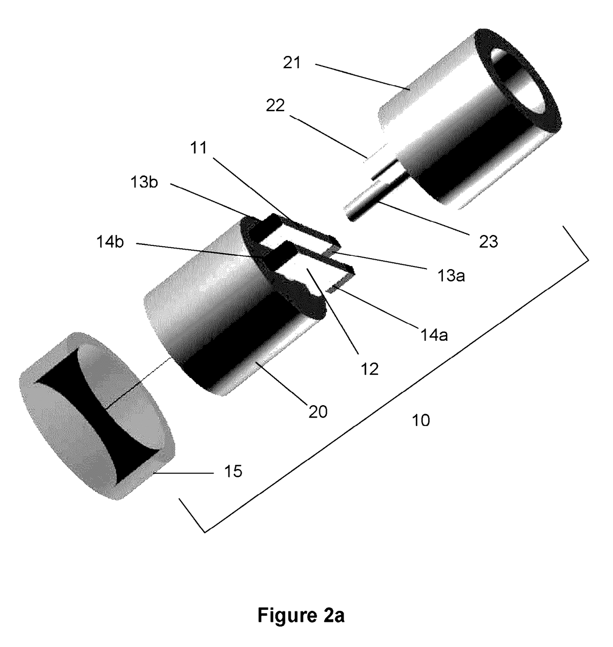
[0013]In the following detailed description of the invention, certain preferred embodiments are illustrated providing certain specific details of their implementation. However, it will be recognized by one skilled in the art that many other variations and modifications may be made given the disclosed principles of the invention.

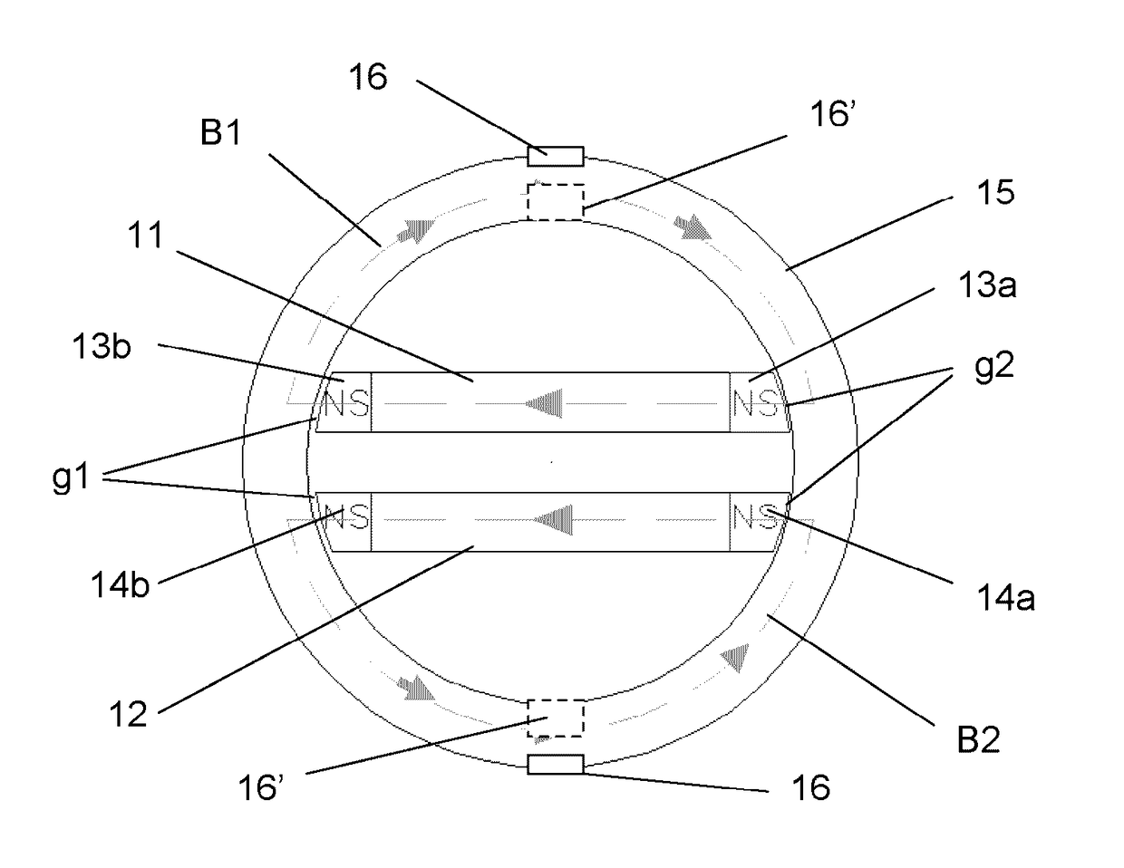
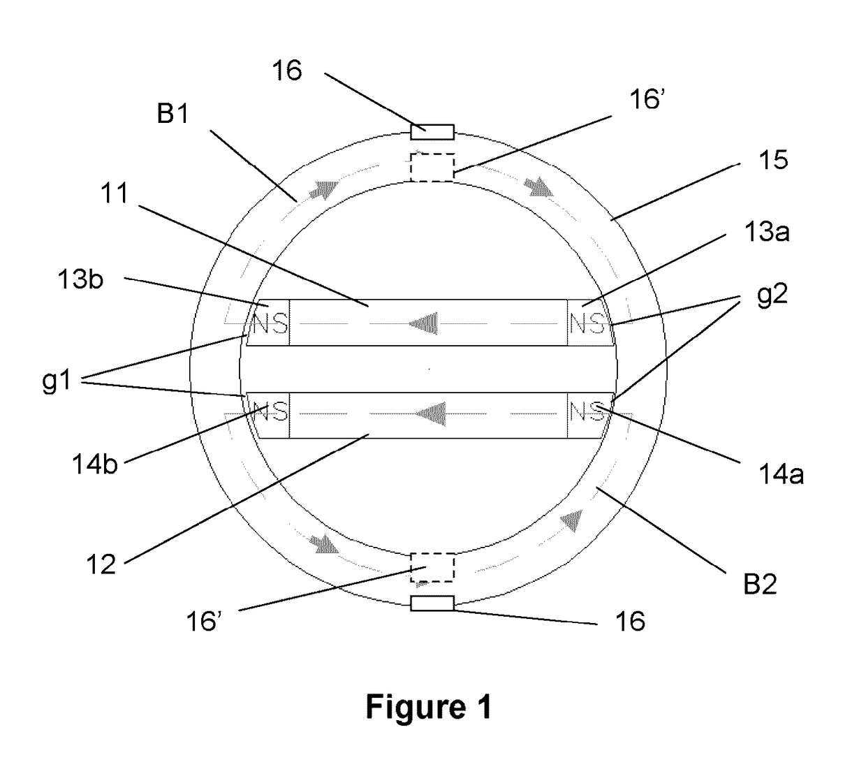
[0014]Referring to the schematic view shown in FIG. 1, the sensor 10 has two flexure beams 11, 12 with magnet pairs 13, 14 attached and configured (pole-wise), as shown. The magnets 13a, 13b and 14a, 14b are attached such that opposing poles are in contact with the flexure beams 11 and 12, respectively. So, for example, if first magnet 13a is mounted with its North pole in contact with flexure beam 11, at the opposite end, second magnet 13b will be mounted with its South pole in contact with the beam. It is necessary that the N-S arrangement, with respect to the flexure beams 11 and 12, stay the same for both beams. The magnets 13a, 13b, 14a and 14b may be of...


PUM

PropertyMeasurementUnit
torqueaaaaaaaaaa
magnetic fieldaaaaaaaaaa
dimensionsaaaaaaaaaa

Abstract

A sensing device for detecting the amount of torque transmitted through a shaft. The device has a first and second section interconnected by a flexure arrangement to which permanent magnets are attached. Deflections of the flexures produce a repeatable and proportional change of magnetic flux which flows in a stationary annular ring that is concentrically mounted with respect to the shaft and separated from it by an air gap. The annular ring is instrumented with an array of magnetic field sensors that measure the changing magnetic flux.

Description

[0001]This U.S. Patent Application claims the priority of U.S. Provisional Patent Application 62 / 088,225, filed on Dec. 5, 2014.TECHNICAL FIELD[0002]This disclosure is in the field of sensors that are placed inline with a rotating shaft to determine the transmitted torque without contact and therefore without the use of slip rings, twist capsules or cable wraps.BACKGROUND[0003]In the control of a shaft driven by a motor or actuator, the position, speed and torque applied to the shaft are parameters of most interest in closing the feedback loop of the system or device. There is, therefore, need for a device that can provide these measurements without contacting the shaft as these are often not very reliable, may be expensive to implement and necessarily require the use of a slip ring or twist capsule to obtain an output electronic signal for processing. One typical contact measurement method uses strain gages which are attached to the shaft of interest; when torsional stress is appli...

Claims


Application Information

Patent Timeline
Patent Type & Authority Applications(United States)
IPC IPC(8): G01L3/10
CPCG01L3/104G01R33/09G01L9/007G01L3/1435
Inventor ROOPNARINE,
Owner ROOPNARINE
Why Eureka
Try Eureka