Signal Transmitter for Pilot Tone Navigation

a technology for signal transmitters and tone navigation, applied in the field of signal transmitters for pilot tone navigation, can solve the problems of power possibly destroying the electronics module of unprotected transmitters, and achieve the effect of simplifying the arrangement of transmitters

Active Publication Date: 2017-06-08
SIEMENS HEALTHCARE GMBH
View PDF2 Cites 26 Cited by
  • Summary
  • Abstract
  • Description
  • Claims
  • Application Information

AI Technical Summary

Benefits of technology

[0038]In one embodiment, a shared housing with a local coil saves on an additional housing, and the arrangement of the transmitter is simplified.
[0039]Conversely, a separate housing allows for a more flexibl

Problems solved by technology

The power possibly destroys an unprotected electronics module of a transmitter (e.g., i

Method used


Image

  • Signal Transmitter for Pilot Tone Navigation
  • Signal Transmitter for Pilot Tone Navigation
  • Signal Transmitter for Pilot Tone Navigation

Examples


Embodiment Construction

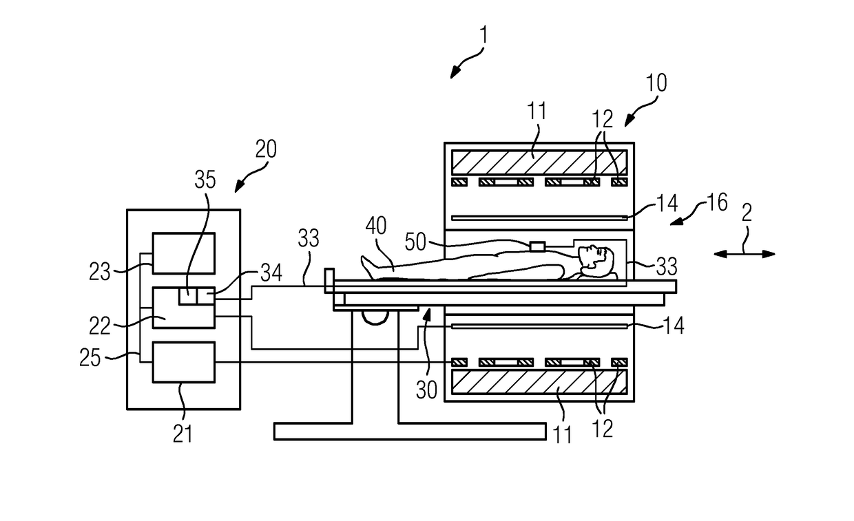
[0045]FIG. 1 shows a schematic representation of one embodiment of a magnetic resonance tomography system 1 with a transmitter 50.

[0046]A magnet unit 10 includes a field magnet 11 that generates a static magnetic field B0 for aligning nuclear spins of test persons or patients 40 in an examination volume. The examination volume is arranged in a leadthrough 16 that extends in a longitudinal direction 2 through the magnet unit 10. The field magnet 11 may be a superconducting magnet that may provide magnetic fields having a magnetic flux density of up to 3T, or even higher in the latest devices. For lower field strengths, however, permanent magnets or electromagnets with normal-conducting coils may also be used.

[0047]The magnet unit 10 includes gradient coils 12 that are configured to overlay the magnetic field B0 with variable magnetic fields in three spatial directions for the spatial differentiation of the captured imaging regions in the examination volume. The gradient coils 12 may ...


PUM


Abstract

A transmitter for pilot tone navigation in a magnetic resonance tomography system includes a power supply and an antenna. The transmitter is configured to transmit a pilot tone signal via the antenna. The transmitter also includes a decoupling element in order to protect a transmitter output from signals that the antenna receives with excitation pulses of the magnetic resonance tomography system during a magnetic resonance tomography. In a method, movement-dependent changes to the pilot tone signal of the transmitter are identified by a controller of the magnetic resonance tomography system.

Description

[0001]This application claims the benefit of DE 10 2015 224 158.0, filed on Dec. 3, 2015, which is hereby incorporated by reference in its entirety.BACKGROUND[0002]The present embodiments relate to a transmitter for pilot tone navigation in a magnetic resonance tomography system and to a method for identifying patient movements.[0003]Magnetic resonance tomography systems are imaging apparatuses that, in order to map an examination object, align the nuclear spins of the examination object with a strong outer magnetic field and by a magnetic alternating field excite the same for precession about this alignment. The precession or return of the spins from this excited state into a state with less energy generates, as a response, a magnetic alternating field that is received via antennae.[0004]With the aid of magnetic gradient fields, a spatial encoding is impressed onto the signals, which then permits an assignment of the received signal to a volume element. The received signal is then ...

Claims


Application Information

Patent Timeline
IPC IPC(8): G01R33/565G01R33/36
CPCG01R33/56509G01R33/3614G01R33/3607
Inventor SCHROTER, STEFFENBOLLENBECK, JANFENCHEL, MATTHIASSPEIER, PETERVESTER, MARKUS
Owner SIEMENS HEALTHCARE GMBH
Why Eureka
Try Eureka