Motor assembly

a technology of motor assembly and rotor, which is applied in the direction of braking system, electric device, transportation and packaging, etc., can solve the problems of generating braking torque immediately, unable to maintain braking torque to stop a motion of a vehicle, and the electric brake will not establish a braking torque, etc., to achieve the effect of maintaining braking torque, reducing the number of parts of the motor assembly, and reducing the efficiency of the feed screw mechanism

Inactive Publication Date: 2017-06-15
TOYOTA JIDOSHA KK +1
View PDF1 Cites 13 Cited by
  • Summary
  • Abstract
  • Description
  • Claims
  • Application Information

AI Technical Summary

Benefits of technology

[0014]Thus, according to the embodiment of the present application, the drive motor is provided with the electromagnetic brake for stopping the rotation of the motor shaft. That is, the motor assembly according to the embodiment may be used not only as a prime mover of an automobile but also as an inboard brake. As described, the motor assembly comprises the thrust generating mechanism and the brake motor. According to the embodiment, therefore, the frictional engagement of the brake stator and the brake rotor may be maintained by the thrust force of the thrust generating mechanism even when the electromagnetic brake is unenergized and hence braking torque is not established by the electromagnetic brake. In other words, the motor assembly according to the embodiment may serve as a parking brake to maintain the braking torque when power is off.
[0016]In the case of arranging the brake rotor, the brake stator, the drive motor, the brake motor and the thrust generating mechanism in order from the protruding end of the motor shaft, those members may be compactly arranged on the common axis to achieve a motor function and a brake function. Consequently, the vehicle using the motor assembly may be downsized and lightened. In addition, the push rod may serve not only as a torque receiving mechanism for restricting the rotation of the brake stator but also as a guide mechanism to reciprocate the brake stator in the axial direction. According to the embodiment, therefore, number of parts of the motor assembly may be reduced to save a manufacturing cost.
[0017]In the case of arranging the drive motor, the brake rotor, the brake stator, the thrust generating mechanism and the brake motor in order from the protruding end of the motor shaft, those members may be compactly arranged on the common axis to achieve a motor function and a brake function. In this case, the vehicle using the motor assembly may be downsized and lightened. In addition, since the thrust force of the thrust generating mechanism is applied directly to the brake stator, a structure of the motor assembly may be simplified.

Problems solved by technology

However, the electromagnetic brake will not establish a braking torque until a magnetizing coil is energized.
That is, a braking torque to stop a motion of a vehicle cannot be maintained during parking while turning the power off.
In this case, however, a braking torque is generated immediately when turn off power to stop the rotation of a driveshaft of the vehicle connected to the motor shaft.
For example, if the power is disconnected during propulsion due to failure, the vehicle would be stopped suddenly.
For this reason, the motor having the electromagnetic brake of this kind is not suitable to be used as a prime mover of automobiles.

Method used


Image

  • Motor assembly
  • Motor assembly
  • Motor assembly

Examples


Embodiment Construction

)

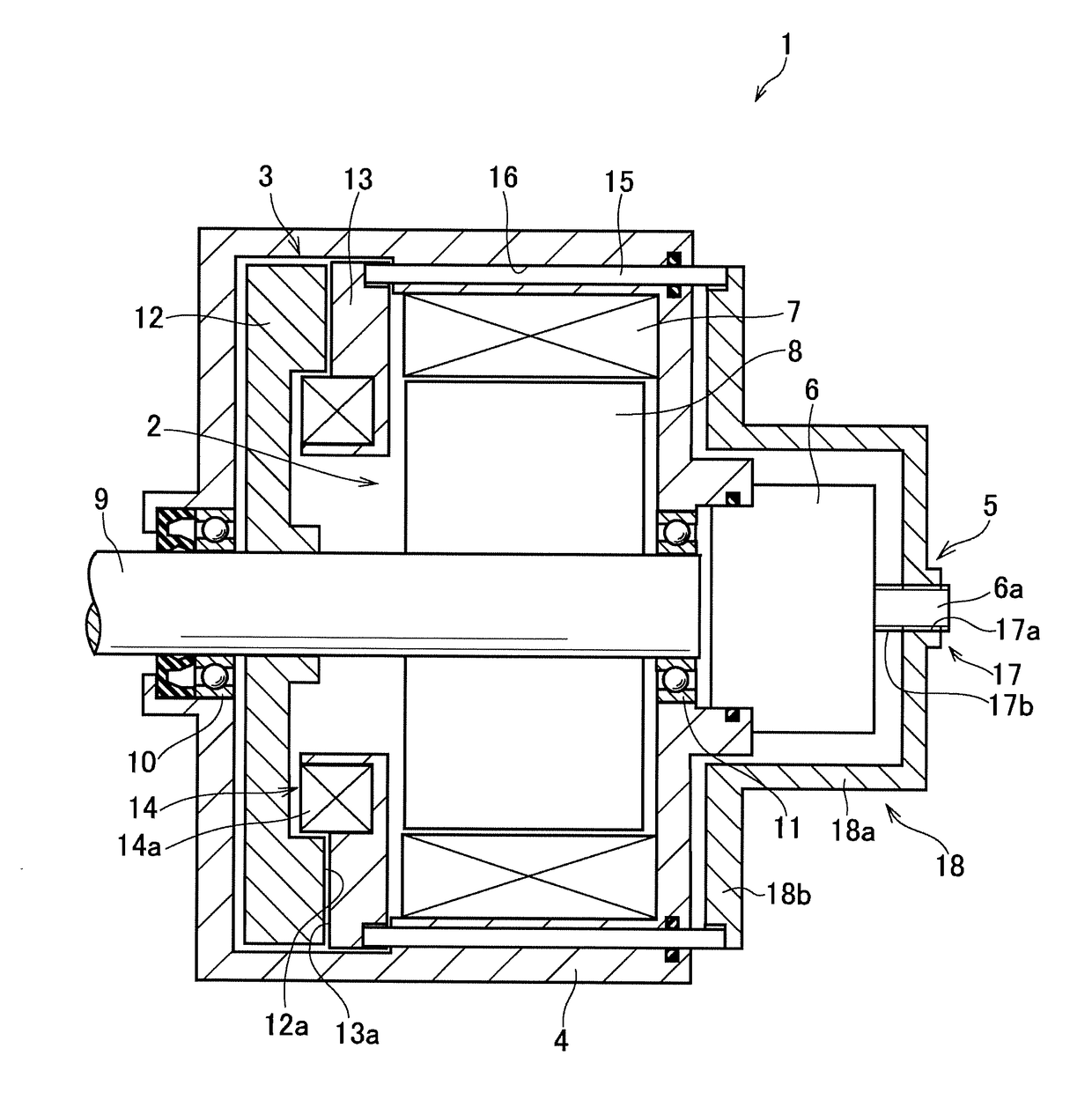
[0023]Preferred embodiments of the present application will now be explained with reference to the accompanying drawings. Referring now to FIG. 1, there is shown a first example of a motor having an electromagnetic brake. As illustrated in FIG. 1, a motor assembly 1 comprises a drive motor 2, an electromagnetic brake 3, a casing 4 holding the drive motor 2 and the electromagnetic brake 3 therein, a thrust generating mechanism 5 and a brake motor 6.

[0024]The drive motor 2 is intended to be used as a prime mover of a vehicle, and for example, a permanent magnet synchronous motor, and an induction motor may be used as the drive motor 2. Specifically, the drive motor 2 comprises a stator 7 that is fixed to an inner face of the casing 4, a motor shaft 9 as an output shaft of the drive motor 2 that is supported by bearings 10 and 11 in a rotatable manner at both ends of the casing 4, and a rotor 8 fitted onto the rotor shaft 9 to be rotated integrally with the rotor shaft 9 but relativel...


PUM


Abstract

A motor having an electromagnetic brake is provided to ensure a braking torque even when power is off. The motor assembly comprises a drive motor and an electromagnetic brake. A thrust generating mechanism translates rotational motion of a brake motor to linear motion to generate thrust force for moving any one of brake stator and brake rotor of the electromagnetic brake thereby maintaining frictional contact therebetween to stop rotation of a motor shaft.

Description

CROSS REFERENCE TO RELATED APPLICATION[0001]The present invention claims the benefit of Japanese Patent Application No. 2015-243941 filed on Dec. 15, 2015 with the Japanese Patent Office, the disclosures of which are incorporated herein by reference in its entirety.BACKGROUND[0002]Field of the Invention[0003]Embodiments of the present application relates to the art of a motor used as a prime mover of automobiles, and especially to a motor having an electromagnetic brake for halting a motor shaft when energized.[0004]Discussion of the Related Art[0005]JP-A-2008-236996 describes a motor provided with an electromagnetic brake. According to the teaching of JP-A-2008-236996, a brake rotor of the electromagnetic brake is fixed to one end of a motor shaft (i.e., an output shaft of the motor). Specifically, the electromagnetic brake taught by JP-A-2008-236996 comprises: the brake rotor including a disc part to which a friction plate is attached and a cylinder part fixed to the motor shaft; ...

Claims


Application Information

Patent Timeline
Patent Type & Authority Applications(United States)
IPC IPC(8): B60L7/24H02K7/00F16D65/18B60T13/74F16D55/02H02K7/106B60L11/18
CPCB60L7/24H02K7/106H02K7/006F16D2121/20B60T13/748F16D55/02F16D65/18B60L11/18H02K7/1023B60L3/0076B60L7/26H02K7/1025F16D55/22Y02T10/64
Inventor ISONO, HIROSHISUGITANI, NOBUYOSHIKUBO, AIZOH
Owner TOYOTA JIDOSHA KK
Why Eureka
Try Eureka