Image acquisition system

a technology of image acquisition and image acquisition, applied in the field of image acquisition system, can solve the problems of affecting the quality of images, so as to achieve the effect of minimizing aberration

Active Publication Date: 2017-06-15
FOTONATION LTD
View PDF5 Cites 7 Cited by
  • Summary
  • Abstract
  • Description
  • Claims
  • Application Information

AI Technical Summary

Benefits of technology

[0020]In embodiments where the surfaces are molded, they car have aspheric shapes to minimize aberrations, and because only a narrow range of wavelengths are of interest (e.g. 750 to 850 nm), it is possible to make each camera almost diffraction-limited.

Problems solved by technology

As well as to unlock a device, it may also be desired to acquire iris images during normal use of the device to continuously or periodically authenticate the user of the device—in such cases it would be undesirable to force the user to hold the device at any distance other than the distance at which they feel comfortable.
However it can be challenging to achieve an acceptably sharp focus depth of more than about 10 cm for lenses used in such systems.
A lens with variable focus might be employed, but this would result in changes in the size of the iris regions extracted.
In addition, using an auto-focus mechanism may be prohibitive in terms of space or for cost constrained applications.
It will also be appreciated that the illumination of an iris at 40 cm will be significantly less than at 15 cm and this can also cause problems with acquiring the required image quality at such distances.
Even then, if there is a need for a resizing of the iris region in each case to normalize iris images acquired at different distances to the same size of iris region before processing, such normalization may be a potential source of artifacts and errors in the underlying biometric pattern.
This can take several seconds and can provide a less than optimal focus depending on the number of focus stops provided by the focus mechanism.
However, using a single auto-focussing system would make it difficult to acquire images of both iris and face regions across a range of 15 cm to 40 cm.
It can be seen therefore that the design of an image acquisition system for iris regions that can capture both iris regions at the same time and across a range of distances suitable for a modern handheld imaging device such as a smartphone presents some challenges.

Method used


Image

  • Image acquisition system
  • Image acquisition system
  • Image acquisition system

Examples


first embodiment

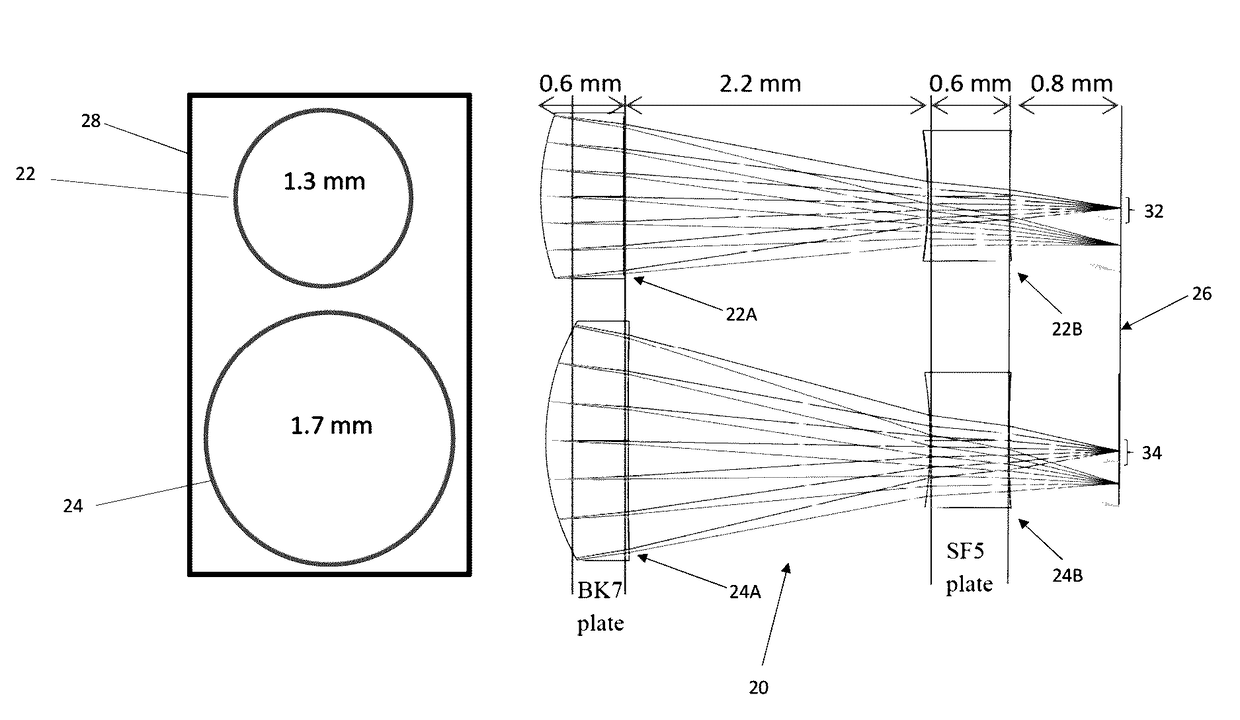
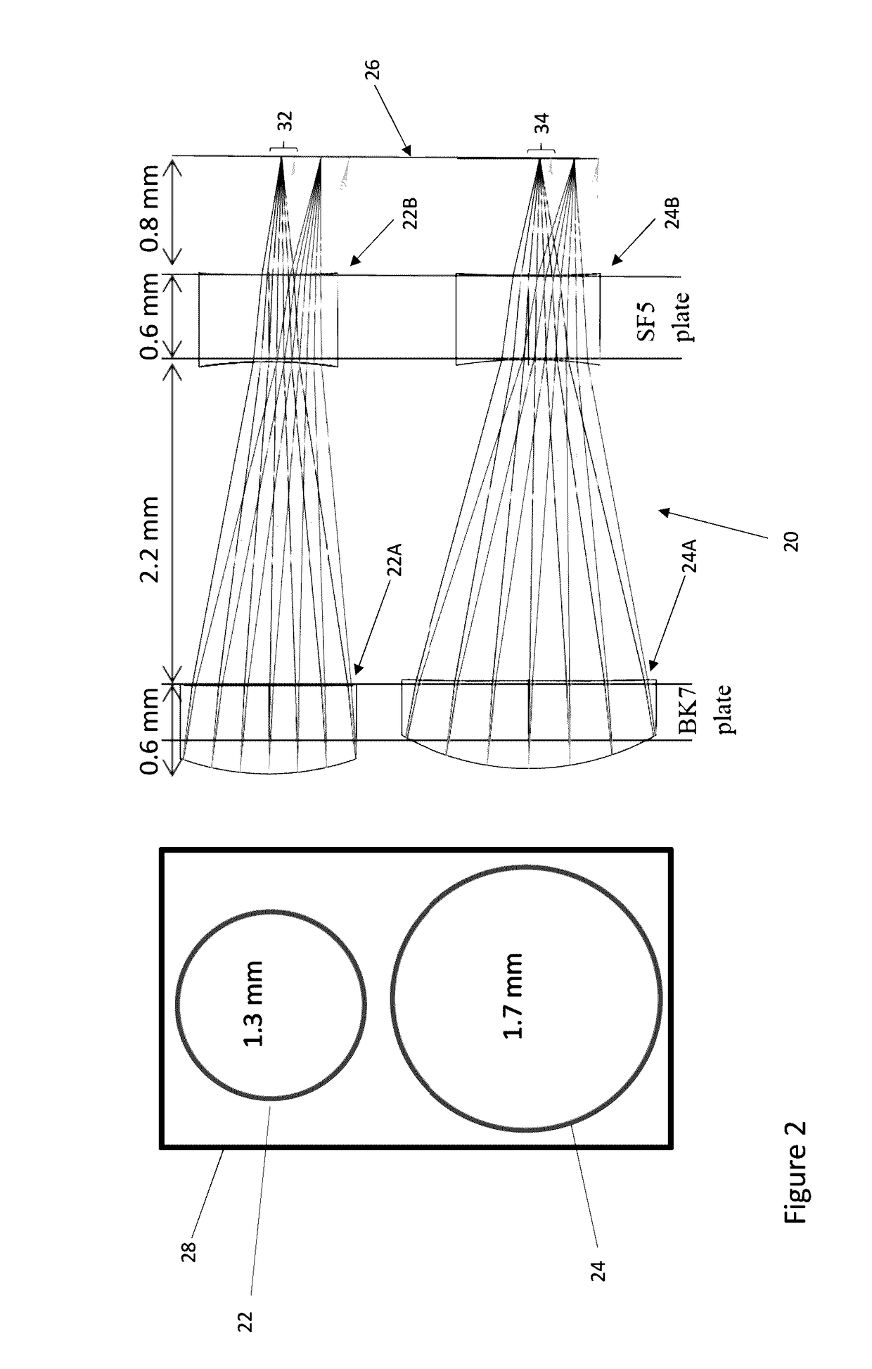
[0030]Referring to FIG. 2, in a first embodiment, the optical system 20 comprises two nearly identical air-spaced lens doublets 22, 24, which are optimised for two different distances covering the overall range 180-350 mm between the eye and the camera. The doublets 22, 24 shown in front view in FIG. 2, each comprise a front optical element 22A, 24A and a rear optical element 22B, 24B. The front optical elements 22A, 24A can each be formed on the same substrate using a wafer level optic (WLO) process such as described below in more detail. Similarly, the rear optical elements 24A, 24B can be formed on the same substrate using a WLO process such as described below in more detail. Typically, a WLO process produces a large array of optical elements on a common substrate and the substrate can then be diced into plates, the outline 28 of one of which is shown in FIG. 2, comprising the optical elements for the lenses of a cluster. Each plate incorporating the front optical elements and re...

second embodiment

[0054]Turning now to FIG. 5 shows a cluster 50 of three lenses 52, 54, 56 each with respective aperture diameters arranged in an irregular grid according to the invention. The following exemplary parameters could be employed for the cluster 50 of FIG. 5:

[0055]Near distance camera (52): F1.8, f=1.7 mm, d=0.95 mm, focus 177 mm (DoF 133-265 mm) Mid-distance camera (54): F1.8, f=3.0 mm, d=1.7 mm, focus 316 mm (DoF 265-390 mm) Far-distance camera (56): F1.8, f=4.0 mm, d=2.2 mm focus 450 mm (DoF 390-530 mm)

[0056]In this example, the three camera cluster of fixed focus cameras covers all focus distances from 133 to 530 mm. As the focal lengths of each of the cameras differ, this cluster of lenses might not be as readily fabricated as those of the other embodiments described herein.

third embodiment

[0057]In a third embodiment, FIG. 6, a cluster 60 comprises 4 elements, a first 62 arranged to have a central object focus distance of, say, 18 cm, the second 64 a central focus distance of 24 cm, the third 66, a central focus distance of 32 cm and the fourth 68, a central focus distance of 42 cm. In this embodiment, the usable focus depth is least for the closest focused camera 62, say 6 cm increasing to 8 cm, 10 cm and 12 cm for each of the lenses 64 to 68. Thus the first camera can span a range from 15-21 cm, the second from 20-28 cm, the third from 27-37 cm and the fourth from 36-48 cm. Within these ranges the iris regions will be in sufficiently sharp focus for high quality acquisition by the image acquisition system.

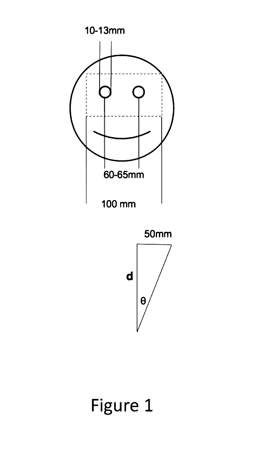
[0058]Again, the field of view of each camera 62 to 68 is different and is determined in this exemplary embodiment for the 10 cm width across the eye region. Thus, for the first camera 62 it will have a FoV, determined by the 18 cm main focus of 31 degrees; for the...


PUM


Abstract

An image acquisition system for acquiring iris images for use in biometric recognition of a subject includes an optical system comprising a cluster of at least 2 lenses arranged in front of a common image sensor with each lens optical axis in parallel spaced apart relationship. Each lens has a fixed focus and a different aperture to provide a respective angular field of view. The lens with the closest focus has the smallest aperture and the lens with the farthest focus has the largest aperture so that iris images can be acquired across a focal range of at least from 200 mm to 300 mm.

Description

FIELD[0001]The present invention relates to an image acquisition system and in particular a system including a plurality of optical assemblies, each arranged to enable the capture of respective images of iris regions used in biometric recognition.BACKGROUND[0002]Biometric recognition based on images of iris regions uses individual radial patterns in the iris. Image acquisition systems for such biometric recognition need to resolve at least 2 lines per mm within the iris pattern in order to provide reliable recognition of a subject. In mobile phones and smartphone in particular, there are two factors that limit direct use of conventional systems of lenses: the mobile phone market strives to minimize the overall camera cost; and making the phone housing as thin as possible.[0003]It is desirable to have a dedicated image acquisition system that can capture images of the iris region of the face in sharp focus across a range of distances with approximately the same size and suitable for ...

Claims


Application Information

Patent Timeline
Patent Type & Authority Applications(United States)
IPC IPC(8): G02B3/00H04N5/33H04N9/04G06K9/00H04N5/225
CPCG02B3/0043G06K9/00604G06K9/0061G02B3/0056H04N5/2256H04N9/04H04N5/332H04N5/2254G02B27/0075G06V40/19G06V40/193H04N23/10H04N23/11H04N23/56
Inventor CORCORAN, PETERBIGIOI, PETRONELDAINTY, CHRISTOPHERGONCHAROV, ALEXANDER
Owner FOTONATION LTD
Why Eureka
Try Eureka