Electric motor

a technology of electric motors and motors, applied in the direction of mechanical energy handling, magnetic circuit rotating parts, magnetic circuit shape/form/construction, etc., can solve the problem achieve the effect of reducing the lifetime of the motor, reducing the weight of the motor, and reducing turbulence and pressure losses

Active Publication Date: 2017-06-15
DYSON TECH LTD
View PDF14 Cites 25 Cited by
  • Summary
  • Abstract
  • Description
  • Claims
  • Application Information

AI Technical Summary

Benefits of technology

[0005]As a result, a motor can be achieved that requires fewer components. The inner wall of the frame supports the rotor assembly, and the inner and outer walls also define a diffuser channel through which the airflow generated by the impeller passes. As such, no separate rotor supporting part or diffuser is required. By reducing the number of components in the motor, the cost of the motor can be reduced, as well as its size and weight.
[0017]The frame may comprise an electrical connection portion formed in the outer wall. The electrical connection portion may be a spade terminal. The electrical connection portion may be a DC reference connection. As a result, no additional connector part is required, and therefore the number of components can be reduced. In turn this can help to minimise the cost of the motor and can also help to reduce the size of the motor.

Problems solved by technology

This can reduce imbalance of the motor, and will minimise unwanted vibration which can affect the performance of the motor, and could reduce its lifetime.

Method used


Image

  • Electric motor
  • Electric motor
  • Electric motor

Examples


Embodiment Construction

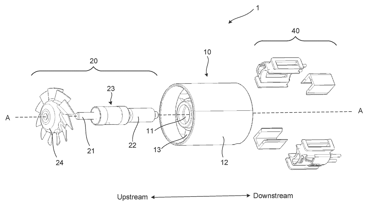
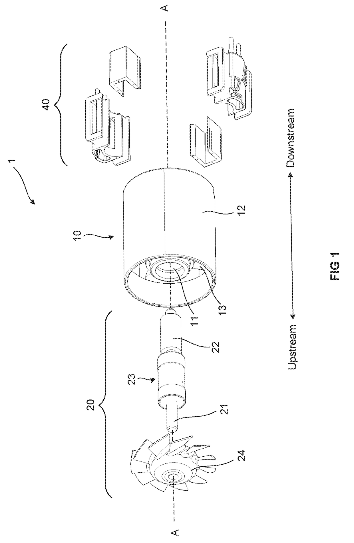
[0025]For the sake of clarity, the term “axial” is intended to mean in the direction of an axis running along a rotational axis of the motor as depicted by axis A-A in FIG. 1. In addition, the directional terms “upstream” and “downstream” referred to herein refer to the direction of airflow through the motor when in use and are further clarified by the double headed arrow in FIG. 1.

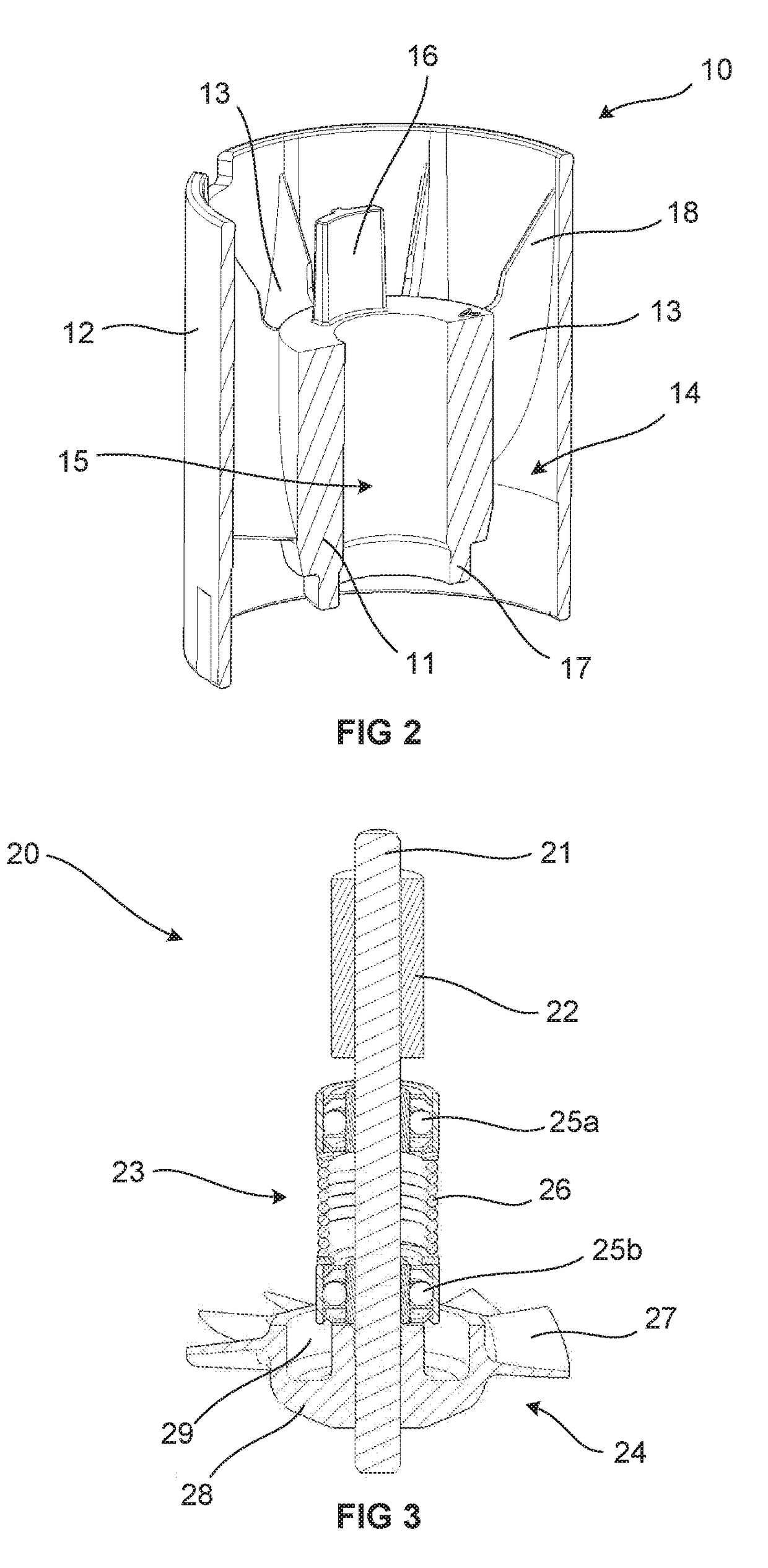
[0026]FIG. 1 is an exploded perspective view of a motor 1. The motor 1 comprises a frame 10, a rotor assembly 20 and a stator assembly 40. A cross section through the frame 10 is shown in FIG. 2. The frame 10 comprises an inner wall 11 and an outer wall 12. The outer wall 12 surrounds the inner wall 11 such that an annular channel 14 is defined between them. A number of diffuser vanes 13 extend between the inner wall 11 and the outer wall 12 through the annular channel 14. The inner wall 11 is shorter in length then the outer wall 12, and the inner wall 11 is positioned such that the outer wall 12 extends...


PUM


Abstract

An electric motor including: a frame; a rotor assembly including a magnet, a bearing assembly, an impeller, and a shaft; and a stator assembly including a stator core and a bobbin. The frame has an inner wall and an outer wall, the outer wall surrounds the inner wall and defines an annular channel between the inner wall and the outer wall, and diffuser vanes extend from the inner wall to the outer wall through the annular channel. The inner wall defines a bore for supporting the rotor assembly, and the outer wall defines a substantially cylindrical outer casing of the motor.

Description

REFERENCE TO RELATED APPLICATIONS[0001]This application claims the priority of United Kingdom Application No. 1521892.8, filed Dec. 11, 2015, the entire contents of which are incorporated herein by reference.FIELD OF THE INVENTION[0002]The present invention relates to an electric motor.BACKGROUND OF THE INVENTION[0003]Electric motors have an extremely wide range of applications, for example from electric drives for vehicles to powering air moving devices such as vacuum motors and fans, and also handheld power tools and other consumer products. With electric motors being incorporated into more and more consumer products, it is important to find ways in which the cost of the electric motor can be kept down where possible. In addition, particularly when being used in handheld products, it is important to find ways in which the size and weight of an electric motor can be minimised. Improvements to electric motors are required that allow for reductions in size, weight and cost of electri...

Claims


Application Information

Patent Timeline
Patent Type & Authority Applications(United States)
IPC IPC(8): H02K7/14H02K5/20H02K1/14H02K7/08H02K1/27
CPCH02K7/14H02K7/08H02K5/20H02K1/141H02K1/27H02K1/18H02K1/2706H02K1/28H02K5/10H02K5/163H02K5/18H02K5/225H02K5/24H02K7/085H02K9/06H02K9/16H02K5/207H02K21/18H02K21/185H02K37/16H02K1/143H02K3/524H02K15/028H02K5/04H02K7/083H02K5/02
Inventor BARNES, ANDREW SIMEONDYMOND, NIGEL YOUATTCLOTHIER, ANDREW CHARLTON
Owner DYSON TECH LTD
Why Eureka
Try Eureka