Active antenna system and methods of determining intermodulation distortion performance

a technology of active antennas and antennas, applied in antenna details, transmission monitoring, antennas, etc., can solve the problems of affecting the performance of desired communications, affecting the performance of wireless communication systems, and decaying series of higher order harmonic frequency components in the frequency domain

Active Publication Date: 2017-06-22
ANALOG DEVICES GLOBAL UNLTD
View PDF2 Cites 28 Cited by
  • Summary
  • Abstract
  • Description
  • Claims
  • Application Information

AI Technical Summary

Benefits of technology

[0029]In an optional example, the at least one processor may be arranged to offset an effect of the applied attenuation or gain factor by applying at least one beam weight compensation value to another transmit module or receiver module. In this manner, a means of compensating for a problematic transmit (and / or receive) module may be achieved by adjustment of, say, a beamform weight compensation value on another transmit module or receiver module.

Problems solved by technology

Wireless communication systems are prone to intermodulation distortion (IMD), affecting performance of desired communications, which is often an artefact of non-linear behaviour of signal processing elements within transmitters / receivers of passive antenna systems.
Passive intermodulation (PIM), is a known issue in passive antenna systems and is caused by signal, or signals, undergoing an undesired non-linear mixing to generate an interference frequency component as an artefact.
Due to the non-linear nature of some signal processing elements within the passive antenna system, fundamental frequency components can become distorted, thereby leading to a decaying series of higher order harmonic frequency components in the frequency domain.
In the case of degraded PIM performance, network operators have forced many antenna manufacturers to replace entire networks of antenna installations at the antenna manufacturers cost.
Regarding active antenna systems (AASs), similar PIM and IMD issues exist.
However, traditional IMD testing techniques cannot be utilised as AASs do not provide at least one connectorised 50Ω port.

Method used


Image

  • Active antenna system and methods of determining intermodulation distortion performance
  • Active antenna system and methods of determining intermodulation distortion performance
  • Active antenna system and methods of determining intermodulation distortion performance

Examples


Embodiment Construction

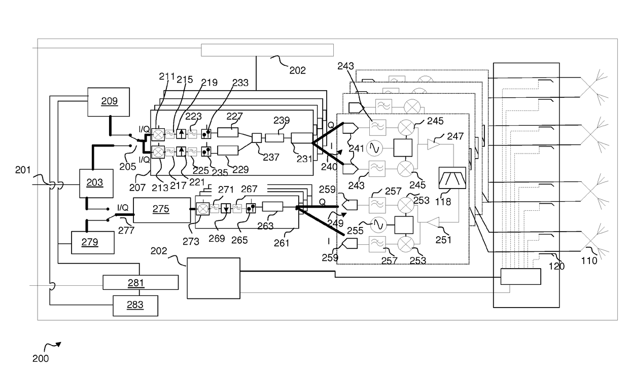
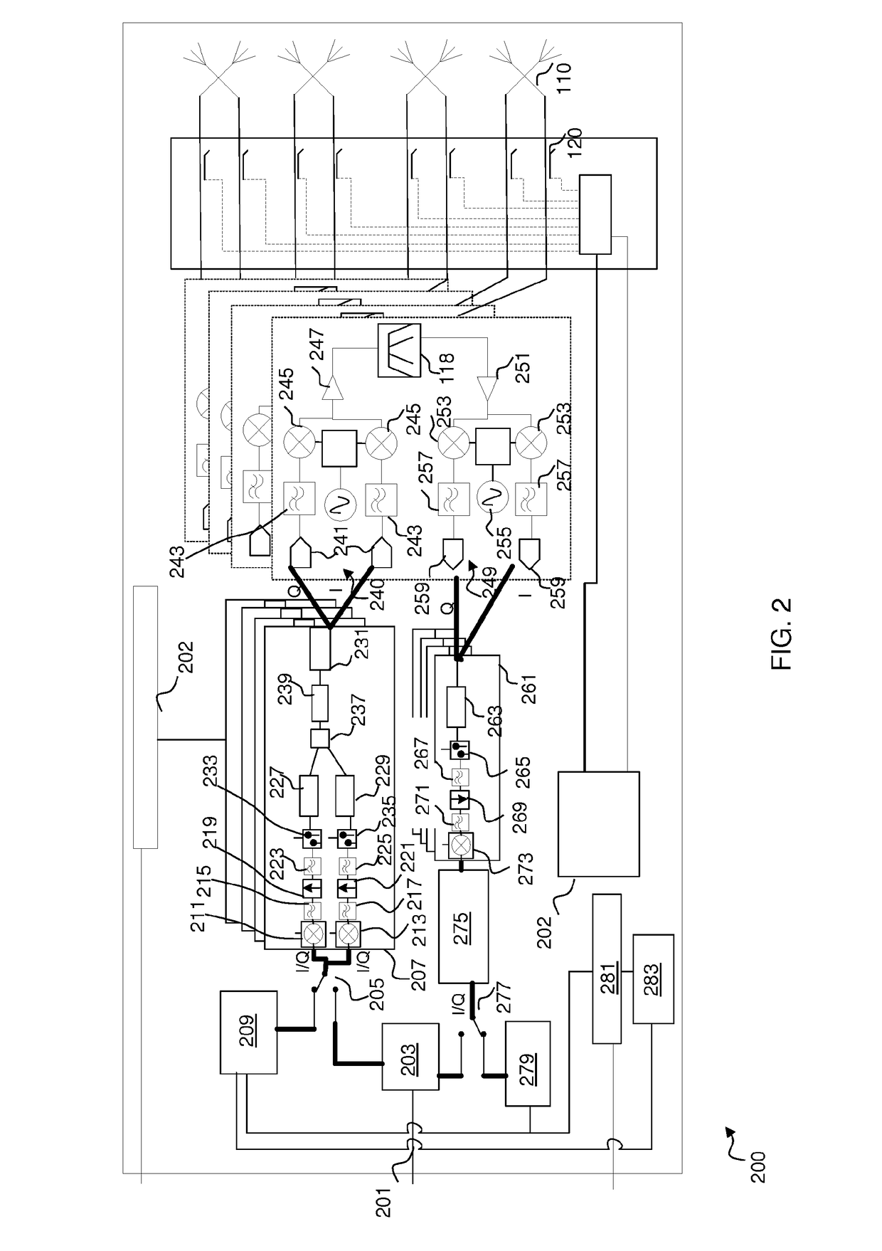
[0039]Example embodiments of the invention are described with reference to smart (or active) antenna technology used in a wireless communication system.

[0040]The following description focuses on embodiments of the invention that are applicable to active antenna arrays employed in Universal Mobile Telecommunication System (UMTS) cellular communication systems and in particular to a UMTS Terrestrial Radio Access Network (UTRAN) operating in a 3rd generation partnership project (3GPP™) system, and evolutions to this standard such as HSPA+ or long term evolution (LTE) system. However, it will be appreciated that the invention is not limited to this particular cellular communication system, but may be applied to any wireless communication system, including satellite communication systems, employing antenna arrangements.

[0041]Example embodiments are described where a processor or multiple processors are arranged to perform a number of functional operations. In some examples, dedicated mod...


PUM


Abstract

An active antenna test system comprising an active antenna unit comprising: a test signal generator arranged to generate at least a first test signal and at least one second test signal; a plurality of transmitter modules operably coupled to the test signal generator wherein the plurality of transmitter modules are arranged to simultaneously process the first test signal and at least one second test signal to produce at least one radio frequency test signal therefrom; and at least one receiver module arranged to process one or more signals falling in at least one spectral band determined to be susceptible to intermodulation distortion products caused by the at least one radio frequency test signal being generated from the first test signal and at least one second test signal; and an intermodulation determination module operably coupled to the at least one receiver module and arranged to determine a first received intermodulation performance. A first transmitter module of the plurality of transmitter modules is operably uncoupled from the test signal generator and at least a first test signal and at least one second test signal re-applied to the remaining transmitter modules, such that the intermodulation determination module determines a second received intermodulation performance in order to determine an intermodulation distortion contribution of the first transmitter module therefrom.

Description

FIELD OF THE INVENTION[0001]The field of this invention relates to an antenna arrangement and methods of testing, and in particular an antenna arrangement and a method of determining an intermodulation distortion performance of one or more components and compensation therefor.BACKGROUND OF THE INVENTION[0002]In a traditional radio network comprising a base station and passive antenna system, for example, at least one connectorised 50Ω port is generally located on the passive antenna system and at least one connectorised 50Ω port is generally located on the basestation. These connectorised 50Ω ports allow signals to be passed there between via at least one 50Ω connectorised cable. The connectors on the base station are typically 7 / 16 DIN radio frequency (RF) connectors or N-type RF connectors.[0003]Wireless communication systems are prone to intermodulation distortion (IMD), affecting performance of desired communications, which is often an artefact of non-linear behaviour of signal ...

Claims


Application Information

Patent Timeline
Patent Type & Authority Applications(United States)
IPC IPC(8): G01R29/10H04B17/12H04B1/04H04B17/10H04B17/14H01Q1/00
CPCG01R29/10H04B17/14H01Q1/00H04B17/104H04B1/0466H04B17/102H04B17/12H04B1/0483H04B17/19H04B1/0475
Inventor O'KEEFFE, CONORMOORE, JOE
Owner ANALOG DEVICES GLOBAL UNLTD
Why Eureka
Try Eureka