
Negative obstacle detector

a detector and negative technology, applied in the field of negative obstacle detectors, can solve the problems of difficult detection of an absence in a pathway (e.g., a hole), exacerbate the problems of conventional systems, and many cannot detect small negative obstacles, so as to achieve high precision and increase the scan time. , the effect of high precision

Active Publication Date: 2017-06-22
RAYTHEON CO
View PDF11 Cites 40 Cited by
  • Summary
  • Abstract
  • Description
  • Claims
  • Application Information

AI Technical Summary

Benefits of technology

The patent describes a system for detecting obstacles in front of a vehicle using laser scanning. The system uses custom scanning patterns to maximize detection of negative obstacles without slowing down the vehicle's speed or performance. The scanning patterns are generated based on current terrain and vehicle information, and can also incorporate historical information on the area the vehicle will traverse. The scanning can be focused on high priority areas to detect small negative obstacles at ranges of 40 meters or greater with sensor heights of 2 meters off the ground. In some embodiments, the system can also evaluate intensity differences to determine the location of an obstacle edge and identify regions free of negative obstacles. The system is efficient in detecting negative obstacles and can be used in various vehicle platforms.

Problems solved by technology

Detecting an absence in a pathway (e.g., a hole) has proven quite difficult.
Further, problems with conventional systems are exacerbated when the autonomous vehicle is operating at speed.
Although, conventional LADAR systems can detect large negative obstacles by scanning a laser beam across a horizontal line, many cannot detect small negative obstacles.
These commercially available systems provide no option to decrease the area associated with the FOR or increase the data refresh rate to capture information faster as terrain or vehicle speed may require.
Conventional horizontal scan LADAR systems cannot detect negative obstacles with such precision because, for example, they cannot adapt the scan region within the FOR, and scene or image based object detection is equally unsuited, as shadows can be incorrectly identified as negative obstacles.
Further, scene or image based object detection can be compromised in low visibility and / or night conditions.
Finally flash based LADAR systems are large and the required laser power to scan the scene prohibits implementation on small platforms.

Method used


Image

  • Negative obstacle detector
  • Negative obstacle detector
  • Negative obstacle detector

Examples


Embodiment Construction

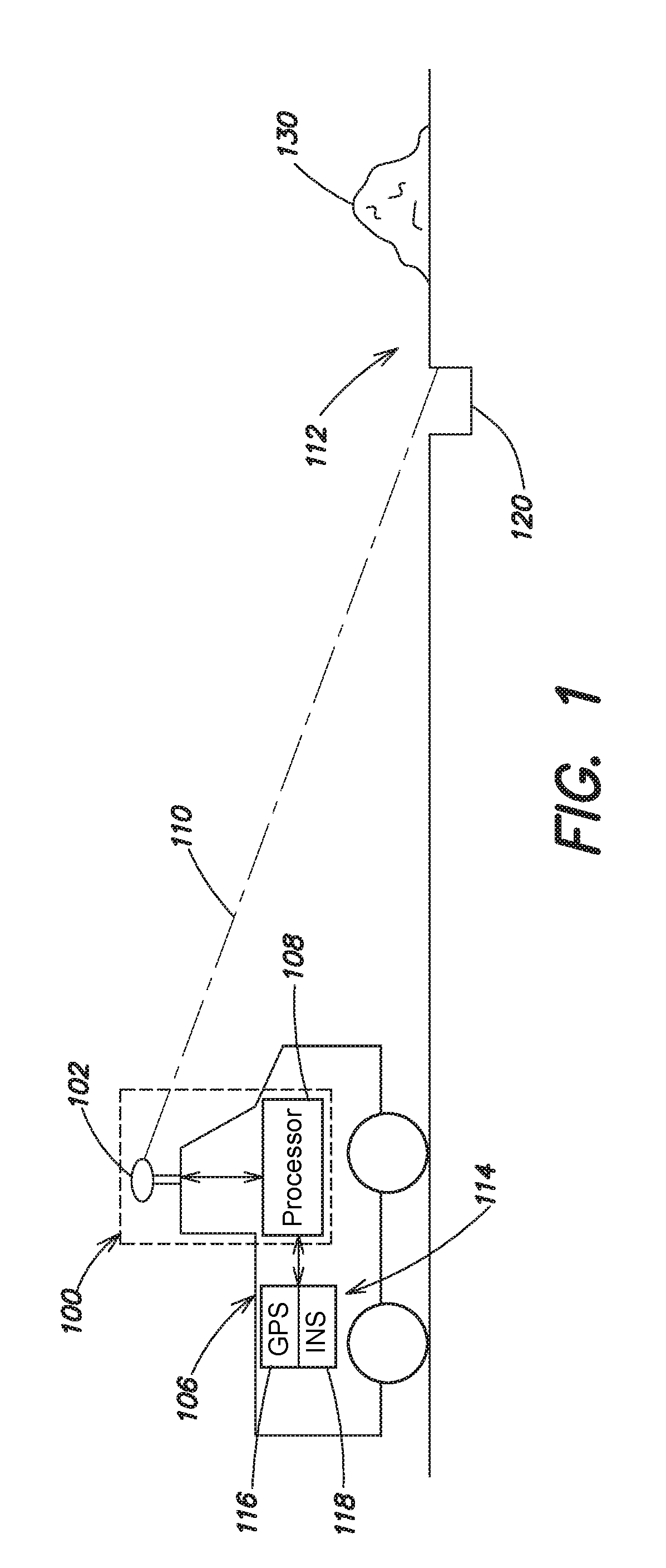
[0031]Aspects and embodiments are directed to a detector that may be mounted on a vehicle to enable autonomous operation of the vehicle. In some examples, the detector can be mounted on manned vehicles and provide assistance (e.g., collision avoidance, object avoidance, etc.) to human drivers. Autonomous vehicle as used herein is intended to include completely autonomous vehicles as well as vehicles with human operators, where driving operation can be assisted or taken over by computer systems.

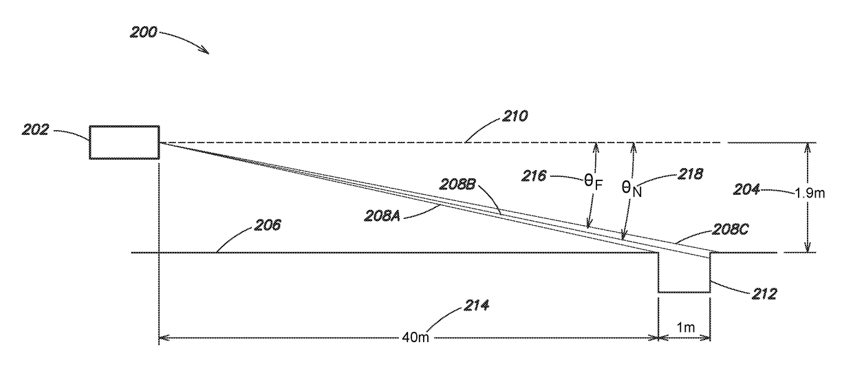
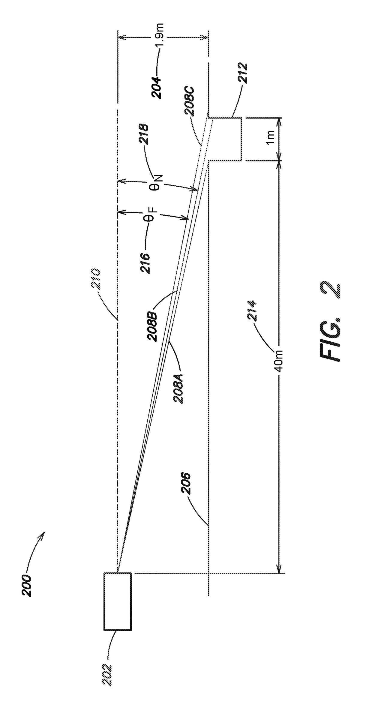
[0032]As discussed in more detail below, embodiments of the detector include a laser scanner device, such as a laser range finder, which may include or be based on a solid-state liquid crystal waveguide, that steers a laser beam from the range finder transmitter to target high priority areas in front of the autonomous vehicle and a detector that provides range to the area illuminated by the laser beam. Discontinuities in the range information can be used to identify obstacles which allow the a...


PUM


Abstract

An obstacle detector configured to identify negative obstacles in a vehicle's path responsive to steering a laser beam to scan high priority areas in the vehicle's path is provided. The high priority areas can be identified dynamically in response to the terrain, speed, and / or acceleration of the vehicle. In some examples, the high priority areas are identified based on a projected position of the vehicles tires. A scan path for the laser, scan rate, and / or a scan location can be dynamically generated to cover the high priority areas.

Description

BACKGROUND[0001]Unmanned ground vehicles (UGVs) include remote-driven or self-driven land vehicles that can carry cameras, sensors, communications equipment, or other payloads. Self-driven or “autonomous” UGVs are essentially robotic platforms that are capable of operating outdoors and over a wide variety of terrain with little or no operator input. To perform optimally, autonomous vehicles should be capable of detecting obstacles in different types of terrain to identify traversable paths. Conventional implementations of autonomous vehicles can include laser detection and ranging (LADAR) sensors that are used to measure the range to each point within a scan area that sweeps across a horizontal line. Other conventional implementations either flood illuminate an entire scene with a single pulse or scan a laser line using rotating mirrors or similar rotating structure. Further, on-board global positioning system (GPS) and inertial navigation system (INS) sensors can provide geo-locati...

Claims


Application Information

Patent Timeline
Patent Type & Authority Applications(United States)
IPC IPC(8): G05D1/00G01S17/42G01S17/93G01S17/931
CPCG05D1/0088G01S17/42G01S17/936G01S7/4802G01S7/4817G01S17/931
Inventor KELLER, SEAN D.UYENO, GERALD P.BECKER, JOHN R.
Owner RAYTHEON CO
Learn More