
Method of controlling purge of fuel cell system for vehicle

a fuel cell system and purge technology, applied in the field of vehicle purge control, can solve the problems of fuel cell system output decline, fuel cell system instability, and deterioration of durability of stacks, so as to prevent the instability of stack output and deterioration of stack durability, accurately confirm the effect of the

Active Publication Date: 2017-06-22
HYUNDAI MOTOR CO LTD
View PDF0 Cites 22 Cited by
  • Summary
  • Abstract
  • Description
  • Claims
  • Application Information

AI Technical Summary

Benefits of technology

The present invention provides methods for controlling purge functions in fuel cell systems, ensuring proper performance and preventing safety accidents. By monitoring the use of hydrogen supply valves, the methods can confirm whether the purge is actually performed and prevent unstable output and deterioration of the stack. This can be achieved without the need for additional sensors or increased costs, and without compromising safety or space within the vehicle.

Problems solved by technology

The water and the nitrogen are factors causing instability in the operation of the fuel cell system, and when the amount of nitrogen within the anode increases, a hydrogen concentration decreases, and thus, reactivity between a catalyst and hydrogen decreases inside the anode.
Accordingly, an output of the fuel cell system decreases, and operation performance becomes unstable.
Further, when water drops flowing into the anode block a flow path formed in a separating plate inside the stack, hydrogen lacks in the corresponding flow path, and thus, a reaction decreases and a carbon carrier is lost, thereby causing a problem of deterioration in durability of the system.
However, such a technique requires additional sensors for the monitoring process, thus causing an increase in component cost, the components may have defects, and an accurate detection is not performed.

Method used


Image

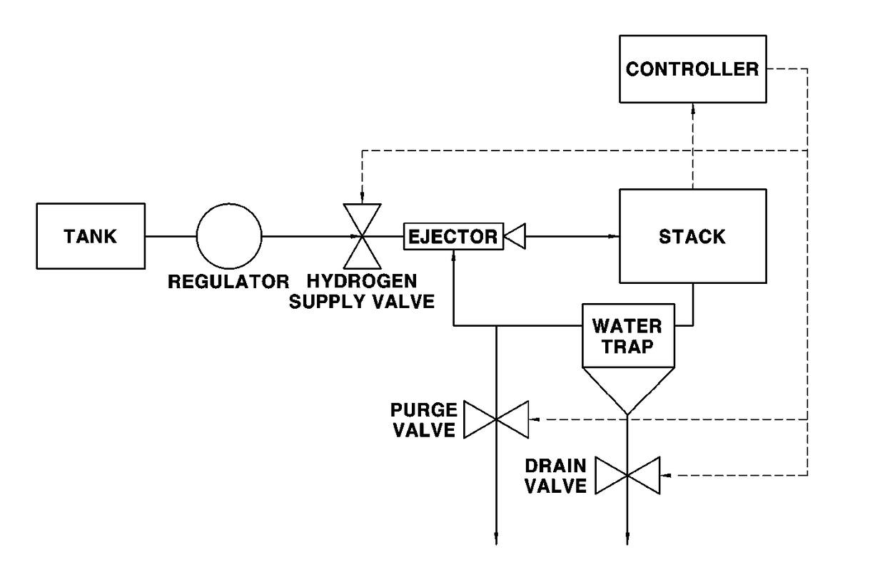
  • Method of controlling purge of fuel cell system for vehicle
  • Method of controlling purge of fuel cell system for vehicle
  • Method of controlling purge of fuel cell system for vehicle

Examples


Embodiment Construction

[0038]It is understood that the term “vehicle” or “vehicular” or other similar term as used herein is inclusive of motor vehicles in general such as passenger automobiles including sports utility vehicles (SUV), buses, trucks, various commercial vehicles, watercraft including a variety of boats and ships, aircraft, and the like, and includes hybrid vehicles, electric vehicles, plug-in hybrid electric vehicles, hydrogen-powered vehicles and other alternative fuel vehicles (e.g. fuels derived from resources other than petroleum). As referred to herein, a hybrid vehicle is a vehicle that has two or more sources of power, for example both gasoline-powered and electric-powered vehicles.

[0039]Although exemplary embodiment is described as using a plurality of units to perform the exemplary process, it is understood that the exemplary processes may also be performed by one or plurality of modules. Additionally, it is understood that the term controller / control unit refers to a hardware devi...


PUM

PropertyMeasurementUnit
pressureaaaaaaaaaa
pressureaaaaaaaaaa
pressureaaaaaaaaaa

Abstract

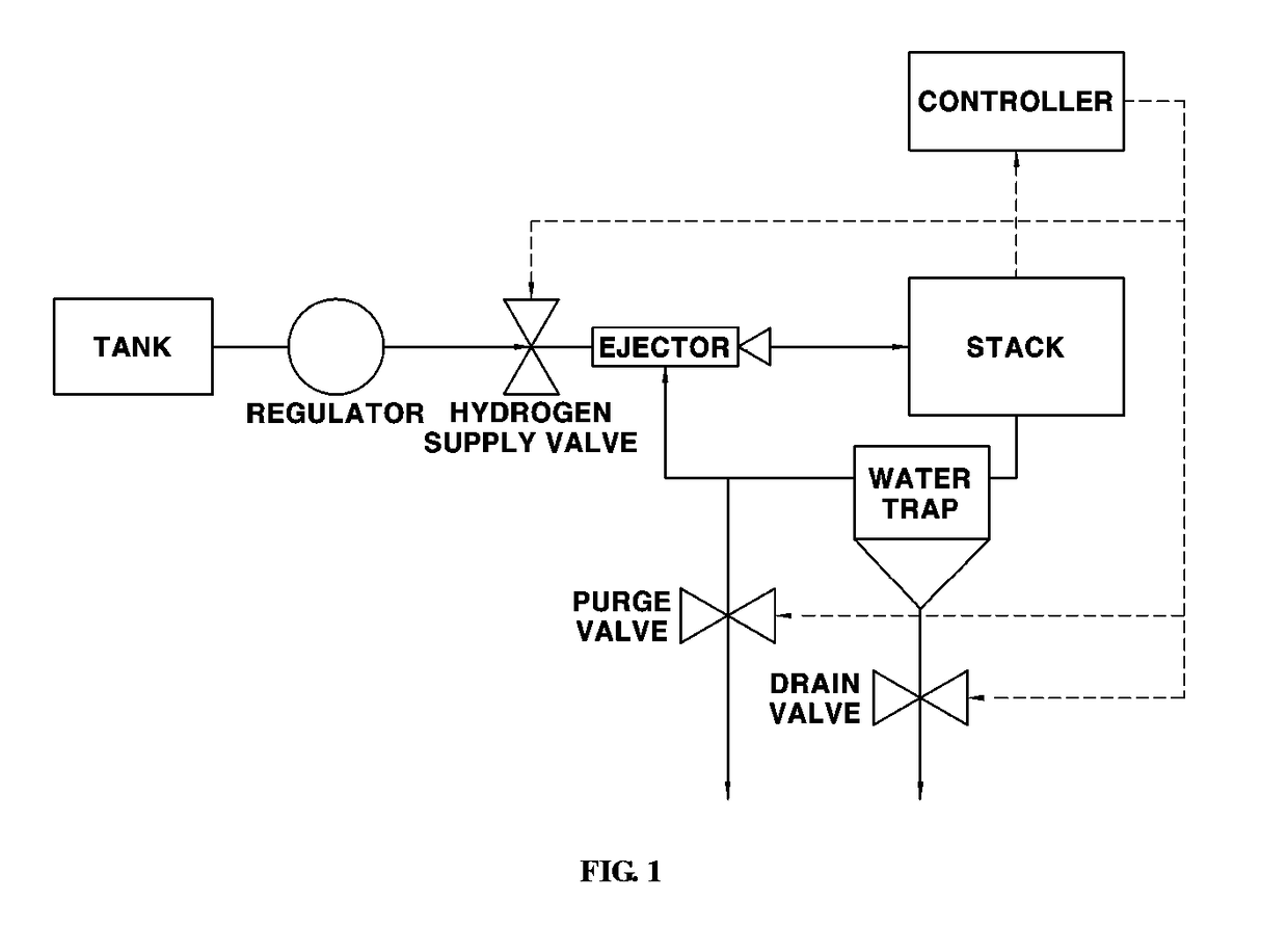
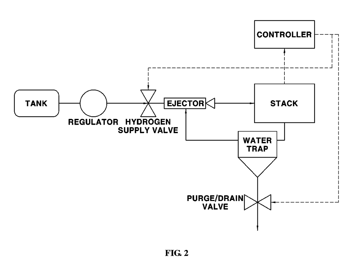
A method of controlling purge of a fuel cell system for a vehicle is provided. The method determines whether a purge function is normally performed in controlling purge of discharging nitrogen, hydrogen, and vapor within an anode of a fuel cell system. Particularly, the method confirms whether purge is performed by measuring a duty or a current applied to a hydrogen supply valve and measuring a change in the duty before and after an application of a purge valve operation command while adjusting a pressure inside the anode, which supplies hydrogen, to be uniform. Further, a hydrogen supply amount supplied into an anode is estimated and a change rate of a hydrogen supply amount supplied to the anode and a hydrogen amount consumed during a generation of the fuel cell system are estimated during a purge function, to determine whether purge is actually performed based on the estimated information.

Description

CROSS-REFERENCE TO RELATED APPLICATION[0001]This application claims under 35 U.S.C. §119(a) the benefit of Korean Patent Application No. 10-2015-0181206 filed on Dec. 17, 2015, the entire contents of which are incorporated herein by reference.BACKGROUND[0002](a) Technical Field[0003]The present disclosure relates to a method of controlling purge of a fuel cell system for a vehicle, and more particularly, to a method of controlling purge, which is capable of performing a purge function of discharging gas inside a stack of a fuel cell system and detecting whether the purge is performed.[0004](b) Background Art[0005]Currently, research has been conducted to enhance a product quality and price competitiveness of a fuel cell system as the commercialization of the fuel cell system increases. Accordingly, a decrease in cost and product quality management factors by decreasing the number of components by combining functions of similar components has been researched.[0006]Theoretically, only...

Claims


Application Information

Patent Timeline
Patent Type & Authority Applications(United States)
IPC IPC(8): H01M8/04664H01M8/04992H01M8/04223
CPCH01M8/04686H01M2250/20H01M8/04992H01M8/04231H01M8/04589H01M8/04656Y02T90/40Y02E60/50
Inventor JUNG, SE KWONKWON, BU KIL
Owner HYUNDAI MOTOR CO LTD
Learn More