
Liquid discharge apparatus and liquid discharge method

a liquid discharge apparatus and liquid discharge technology, applied in the direction of printing, other printing apparatus, applying layer means, etc., can solve the problem that the nozzle is likely to have a low ink discharge performan

Active Publication Date: 2017-06-29
SEIKO EPSON CORP
View PDF5 Cites 6 Cited by
  • Summary
  • Abstract
  • Description
  • Claims
  • Application Information

AI Technical Summary

Benefits of technology

The invention is a liquid discharge apparatus that generates liquid droplets for industrial applications such as coating or printing. The apparatus includes a head unit with a nozzle array and a liquid droplet generating unit. The liquid droplets are separated from the liquid columns using a laser beam that is directed in a way that reduces drying and accumulation near the nozzle openings. The laser beam is also directed in a way that reduces energy that passes between the liquid columns, resulting in efficient energy application and reduced degradation in liquid discharge performance. The liquid droplets are then fixed to the target object by sintering or solidifying powder in the liquid. Overall, the liquid discharge apparatus has improved efficiency and stability compared to previous methods.

Problems solved by technology

However, in technology disclosed in JP-A-6-64161, since the heat generating unit is provided in a portion of the nozzle from which ink is discharged, dried ink is likely to be attached and accumulated on an edge of the nozzle and thus the nozzle is likely to have a low ink discharge performance.

Method used


Image

  • Liquid discharge apparatus and liquid discharge method
  • Liquid discharge apparatus and liquid discharge method
  • Liquid discharge apparatus and liquid discharge method

Examples


first embodiment

A. First Embodiment

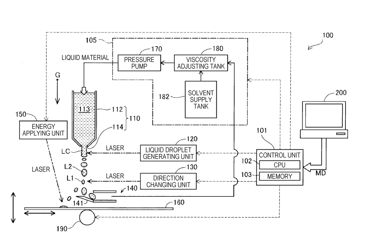
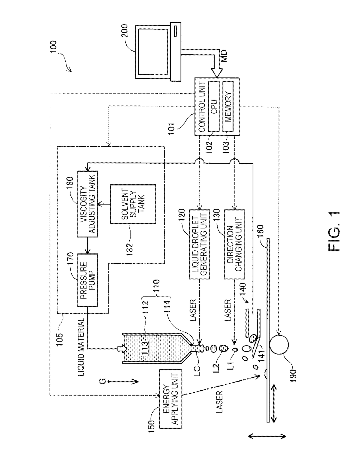
[0031]FIG. 1 is a diagram depicting a schematic configuration of a liquid discharge apparatus 100 according to a first embodiment of the invention. In FIG. 1, arrow G represents the direction of gravitational force (vertical direction) when the liquid discharge apparatus 100 is disposed in a normal service state. Arrow G representing the vertical direction is appropriately shown in the drawings to which the following description is referred.

[0032]The liquid discharge apparatus 100 of the embodiment is a so-called 3D printer, discharges a liquid material from the head unit 110 toward a forming stage 160, stacks layers formed of a corresponding solidified primary material on the forming stage 160, and produces a three-dimensional object. The liquid discharge apparatus 100 includes a control unit 101, a liquid supply unit 105, a liquid droplet generating unit 120, a direction changing unit 130, a collecting unit 140, an energy applying unit 150, and a moving mechanis...

second embodiment

B. Second Embodiment

[0069]FIG. 8 is a diagram schematically depicting a configuration of a liquid droplet generating unit 120A included in a liquid discharge apparatus 100A of the second embodiment. Similar to FIG. 5, FIG. 8 schematically illustrates the head unit 110 and the liquid droplet generating unit 120A, when the liquid discharge apparatus 100A of the second embodiment is viewed from below in the vertical direction. FIG. 8 schematically illustrates, as a hatched portion, a region that is scanned with the laser beam emitted from the liquid droplet generating unit 120.

[0070]The liquid discharge apparatus 100A of the second embodiment has substantially the same configuration as the liquid discharge apparatus 100 described in the first embodiment, except for a different configuration of the liquid droplet generating unit 120A. The liquid droplet generating unit 120A of the second embodiment is positioned in the direction obliquely intersecting with the arrangement direction of t...

third embodiment

C. Third Embodiment

[0072]FIG. 9 is a diagram schematically depicting a configuration of a liquid discharge apparatus 100B of the third embodiment of the invention. Similar to FIG. 5, FIG. 9 schematically illustrates a head unit 110B and the liquid droplet generating unit 120, when the liquid discharge apparatus 100A of the second embodiment is viewed from below in the vertical direction. FIG. 9 illustrates an axial line AXa that represents the arrangement direction of the nozzles 114 in a first nozzle array 115a and an axial line AXb that represents the arrangement direction of the nozzles 114 in the second nozzle array 115b. The liquid discharge apparatus 100B of the third embodiment has substantially the same configuration as the liquid discharge apparatus 100 of the first embodiment, except that the head unit 110B has the two nozzle arrays 115a and 115b.

[0073]The first nozzle array 115a and the second nozzle array 115b are provided to be parallel to each other and the arrangemen...


PUM


Abstract

A liquid discharge apparatus includes: a head unit that has a nozzle array in which a plurality of nozzles are arranged, that discharges a liquid from each of the plurality of nozzles, and that causes liquid columns to extend downwardly; a liquid droplet generating unit that irradiates at least the two liquid columns with a laser beam in a direction obliquely intersecting with the arrangement direction when viewed from the center of the nozzle array and that separates liquid droplets from the liquid column; and a direction changing unit that applies energy to the liquid droplets and changes flying directions of the liquid droplets.

Description

BACKGROUND[0001]1. Technical Field[0002]The present invention relates to a liquid discharge apparatus and a liquid discharge method.[0003]2. Related Art[0004]As an aspect of a liquid discharge apparatus that discharges a liquid, an ink jet printer that discharges ink and produces printed matter, or a 3D printer that discharges a liquid material and forms a three-dimensional object is known. For example, an ink jet printer disclosed in JP-A-6-64161 causes a heat generating unit (laser) provided in a portion of the nozzle to change a viscosity of a liquid column of ink that is formed at a nozzle and to generate pulsation in the liquid column, thereby continually forming ink particles.[0005]However, in technology disclosed in JP-A-6-64161, since the heat generating unit is provided in a portion of the nozzle from which ink is discharged, dried ink is likely to be attached and accumulated on an edge of the nozzle and thus the nozzle is likely to have a low ink discharge performance. In ...

Claims


Application Information

Patent Timeline
Patent Type & Authority Applications(United States)
IPC IPC(8): B41J2/02B41J11/00
CPCB41J11/002B41J2/02B41J2/03B41J2002/033B33Y30/00B29C64/209
Inventor SUGAI, KEIGO
Owner SEIKO EPSON CORP
Learn More