

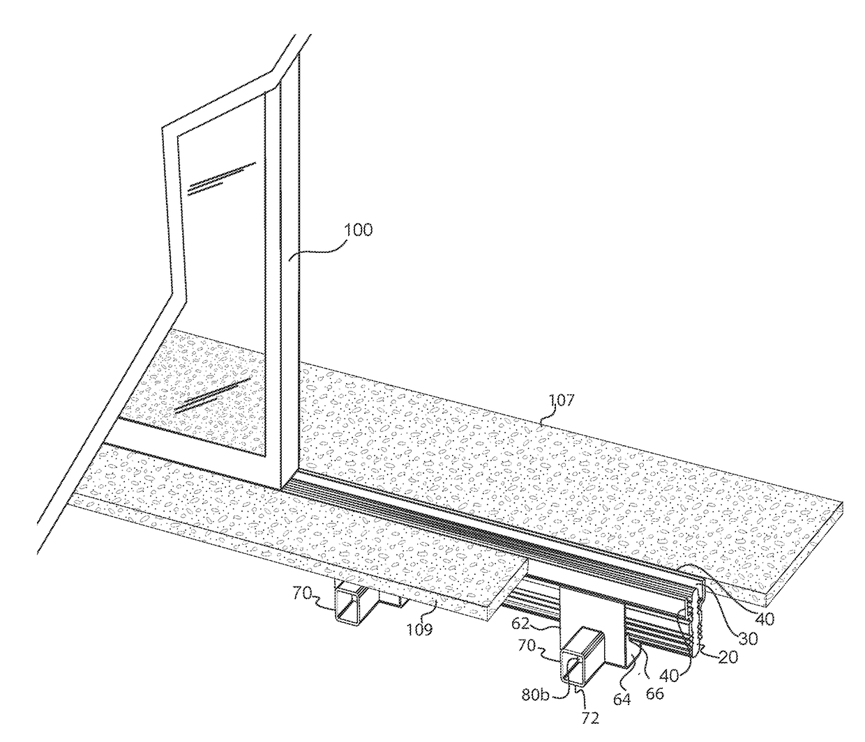
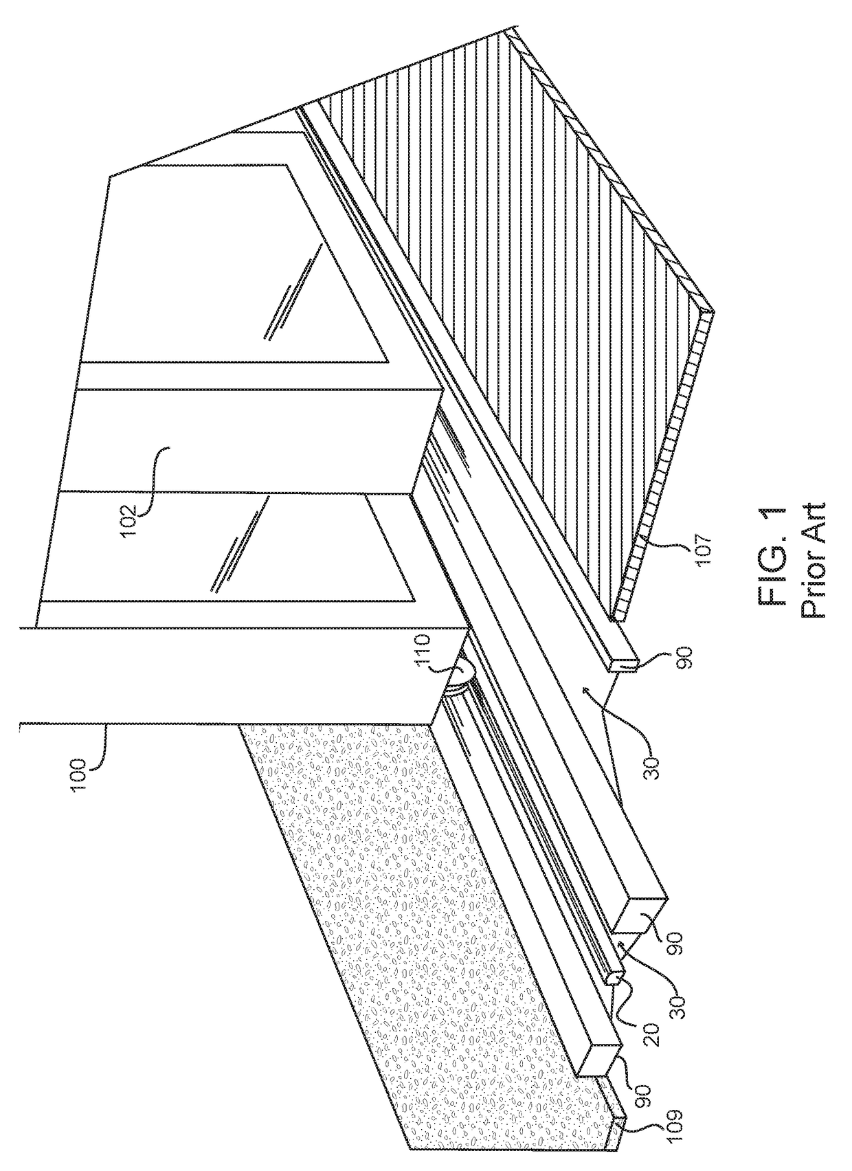
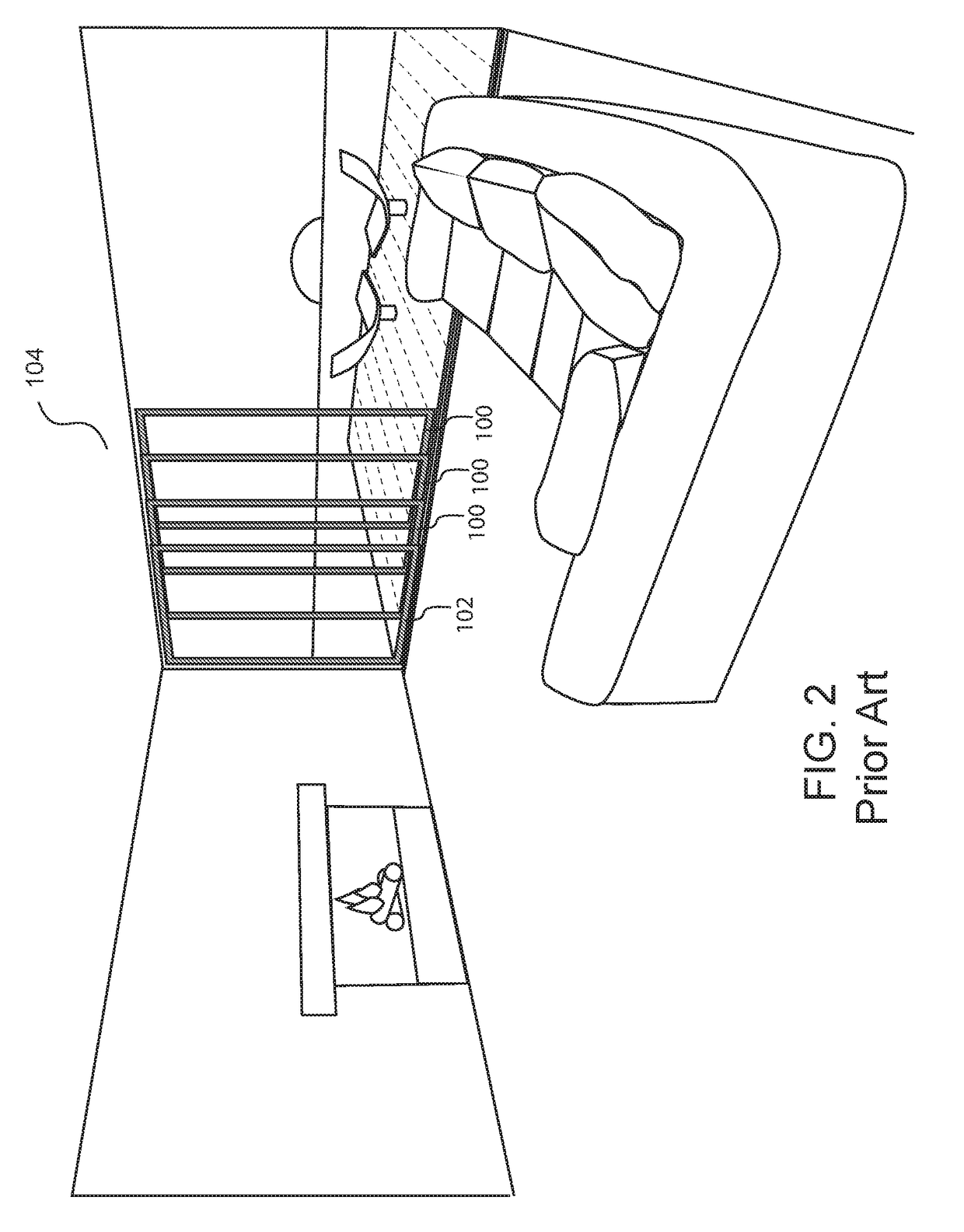
Drain track devices, assemblies and systems
a technology of assembly and track device, which is applied in the direction of door/window fittings, wing accessories, wing arrangements, etc., can solve the problems of increasing the need for systems, increasing the difficulty of intrusion, and reducing the effect of rain and condensation around doors
- Summary
- Abstract
- Description
- Claims
- Application Information
AI Technical Summary
Benefits of technology
Problems solved by technology
Method used
Image

Examples
Embodiment Construction
[0041]While the specification concludes with claims defining the features of the invention that are regarded as novel, it is believed that the invention will be better understood from a consideration of the description in conjunction with the drawings. As required, detailed embodiments of the present invention are disclosed herein; however, it is to be understood that the disclosed embodiments are merely exemplary of the invention which can be embodied in various forms. Therefore, specific structural and functional details disclosed herein are not to be interpreted as limiting, but merely as a basis for the claims and as a representative basis for teaching one skilled in the art to variously employ the inventive arrangements in virtually any appropriately detailed structure.
[0042]Further, the terms and phrases used herein are not intended to be limiting but rather to provide an understandable description of the invention. Unless otherwise noted, the terms used herein are to be under...
PUM
 Abstract
Description
Claims
Application Information