Eureka AIR delivers breakthrough ideas for toughest innovation challenges, trusted by R&D personnel around the world.

Switch unit, ethernet network, and method for activating components in an ethernet network

Active Publication Date: 2017-06-29
VOLKSWAGEN AG
View PDF0 Cites 0 Cited by
  • Summary
  • Abstract
  • Description
  • Claims
  • Application Information

AI Technical Summary

Benefits of technology

The invention is a switch unit and network for Ethernet that allows for faster and more energy-efficient wakeup of connected components. The switch unit has a microprocessor and a memory unit with allocation rules for each input / output. When a bus activity is detected, the inputs / outputs associated with the detected activity are quickly read from the memory unit and woken up, much faster than setting up the actual communication link. The switch unit can also be designed to re-specify which components to wake up based on the activity of one component. The signal detectors and generators as well as the memory unit are continuously supplied with voltage to ensure quick wakeup.

Problems solved by technology

This gains a significant amount of time compared to the step-by-step wakeup approach.

Method used


Image

  • Switch unit, ethernet network, and method for activating components in an ethernet network
  • Switch unit, ethernet network, and method for activating components in an ethernet network
  • Switch unit, ethernet network, and method for activating components in an ethernet network

Examples


Embodiment Construction

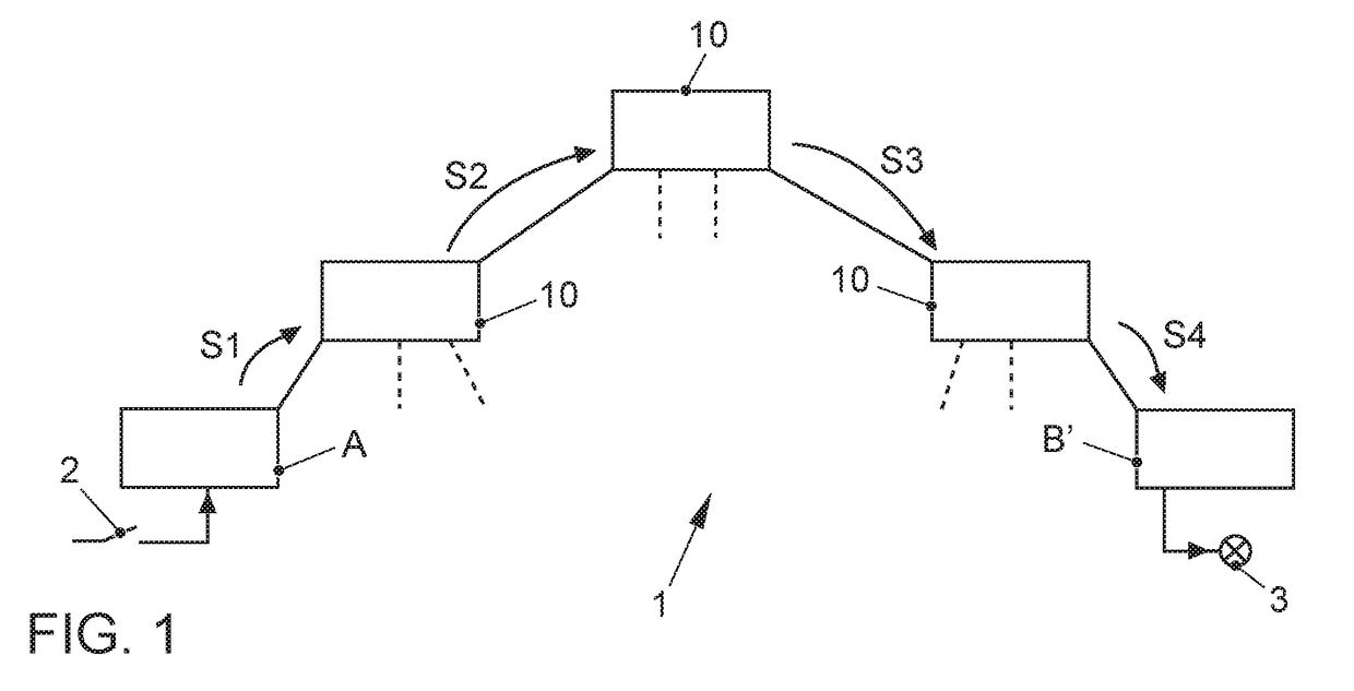
[0023]Part of an Ethernet network 1 is illustrated in FIG. 1, which includes a first control unit A and a second control unit B′, which are connected to each other via three switch units 10, the dashed line on switch units 10 being intended to show that the latter may be connected to additional control units and / or switch units. A switch or sensor 2 is assigned to control unit A, wherein an actuator 3 is to be activated by control unit B′ upon the detection of a sensor signal or the actuation of the switch.

[0024]Assuming that all control units A, B′ and all switch units 10 are asleep, control unit A is first woken up by sensor 2 or the switch. After control unit A is woken up, the latter transmits a communication signal to connected switch unit 10 in a first step S1 with the request to set up a data connection with control unit B. At the address of control unit B′, switch unit 10 now detects that superordinate switch unit 10 is required for the data connection and, in a second step ...


PUM


Abstract

A switch unit for an Ethernet network having a switch and a microprocessor, the switch including at least three ports, which are connected to inputs and outputs of the switch unit, a signal detector and generator for detecting and initiating a bus activity being arranged in each case between the ports and the inputs and outputs of the switch unit. For each input and output an allocation rule to the other inputs and outputs of the switch unit is stored in a memory , the switch unit being designed such that when a bus activity is detected at a signal detector and generator, the assigned inputs and outputs of this input and output are read out from the memory and the associated signal detectors and generators are woken up so that they generate a bus activity at their inputs and outputs.

Description

[0001]This nonprovisional application is a continuation of International Application No. PCT / EP2015 / 066287, which was filed on Jul. 16, 2015, and which claims priority to German Patent Application No. 10 2014 216 444.3, which was filed in Germany on Aug. 19, 2014, and which are both herein incorporated by reference.BACKGROUND OF THE INVENTION[0002]1. Field of the Invention[0003]The invention relates to a switch unit, an Ethernet network comprising a switch unit and a method for activating components in an Ethernet network.[0004]2. Description of the Background Art[0005]Ethernet networks have long been known from the field of computer science, and their use in motor vehicles has been contemplated in recent years. One advantage of Ethernet networks over conventional automotive networks, such as CAN or FlexRay, is that they very easily permit subnetwork operation, so that unnecessary control units may be switched off or placed in sleep mode. This makes it possible to correspondingly sa...

Claims


Application Information

Patent Timeline
IPC IPC(8): H04L12/931H04L12/40H04L12/46G06F13/14H04L12/12H04L12/937G06F15/173
CPCH04L49/351H04L49/253H04L12/40G06F15/1735G05B2219/25012H04L12/12H04L12/4625G06F15/17343G05B2219/25174G06F13/14Y02D10/00Y02D30/50
Inventor KRIEGER, OLAFCLAUS, LOTHARHOFFMANN, CHRISTOPH
Owner VOLKSWAGEN AG
Why Eureka
Eureka Blog
Learn More