Sealing connection assembly for a sampling device

a sampling device and sealing connection technology, applied in the direction of couplings, laboratory glassware, instruments, etc., can solve the problems of reducing the risk of manipulation and reuse of sampling devices, affecting the sealing effect, so as to reduce the risk of manipulation and reuse of sampling devices. , the effect of reducing the risk of manipulation and reus

Inactive Publication Date: 2017-07-06
PROVTAGAREN
View PDF0 Cites 0 Cited by
  • Summary
  • Abstract
  • Description
  • Claims
  • Application Information

AI Technical Summary

Benefits of technology

[0015]An object of the present invention is to eliminate the above-mentioned problems and provide a sealing connection assembly for a test tube lid, for a tube connection, for a sampling device for environmental, laboratory and medical analysis, etc, wherein improved sampling with higher liability in a fluid flow for the analysis of one or more substances of interest is provided and wherein the risk of manipulation and reuse of the sampling device is reduced or eliminated.

Problems solved by technology

The quality of the sealing in the sense that it is reliably fluid-tight also for long periods of time, is especially important in laboratory environments or in medical environments, since leakage could lead to faulting measurements, damage to equipment or wrong dosage or contamination of drugs to a patient.
This may result in a fluid tight sealing when the sealing is closed, but after a while, especially if temperature and pressure changes gave occurred, the materials of the sealing will give in to some extent and the sealing will leak.
If leakage occurs during the measurement in such a way that the gas flow may circumvent the filter, the measurement will be inaccurate.
Currently used samplers show some structural drawbacks.
By rotating either the filter holder or the adsorption tube, or both, when assembling the sampler components, the filter may be sheared or broken due to the rotational forces induced, and leaks may occur.
The filter may also unintentionally shift in position during the rotation of the sampler components creating large gaps around the filter, thereby making the measurement inaccurate.
A further problem is that when storing the assembled sampler, the pressure exerted on the filter may alter due to ageing of the filter.
Thereby the sealing properties may be negatively affected.
Otherwise, the measurements may be negatively affected and destroyed by the undesired diffusion into the sampler.
Thus, as sampling in several environments may be very expensive and require highly accurate measurement results, it is of great importance that the sampler is fluid-tight against the outside environment when assembled, in particular during handling and transport before and after the measurements.
Another problem in connection with use of sampling devices for the measurement of air-borne compounds in a fluid flow is the risk that the sampling device is tampered or manipulated during handling thereof, i.e. during the period from when it is transported from the supplier or the analysis laboratory to the user, is subjected to the sampling step by the user, and then is transported from the user to the analysis laboratory.
However, it has turned out that sampling devices have been manipulated or tampered with during the transports or by the user before, during, and after the sampling step, either unintentionally or intentionally.
This of course leads to false or inaccurate analysis results in the end.
Another problem is that when the sampling device has been used once it is further used one or more times after the analysis step of the laboratory.
When such a sampling device is sent to a user for sampling, the interior surfaces thereof normally are contaminated with different compounds from the previous sampling, and the analysis results finally obtained at the analysis laboratory will be false or inaccurate.

Method used


Image

  • Sealing connection assembly for a sampling device
  • Sealing connection assembly for a sampling device
  • Sealing connection assembly for a sampling device

Examples


Embodiment Construction

[0033]The expression “fluid flow direction” used throughout the application text is intended to mean the axial direction in relation to the cross-section of the sealing connection assembly.

[0034]The expression “fluid flow” used throughout the application text is intended to mean a flow of a gas or a liquid, which also may contain components in solid form, e.g. fluidized particles and aerosols. One example of a fluid is an air flow containing small particles having the substances to analyze bound to their surfaces. Another example of a fluid flow is a water flow containing the substances to analyze, e.g. a drinking water flow, and flows in connection with purification plants.

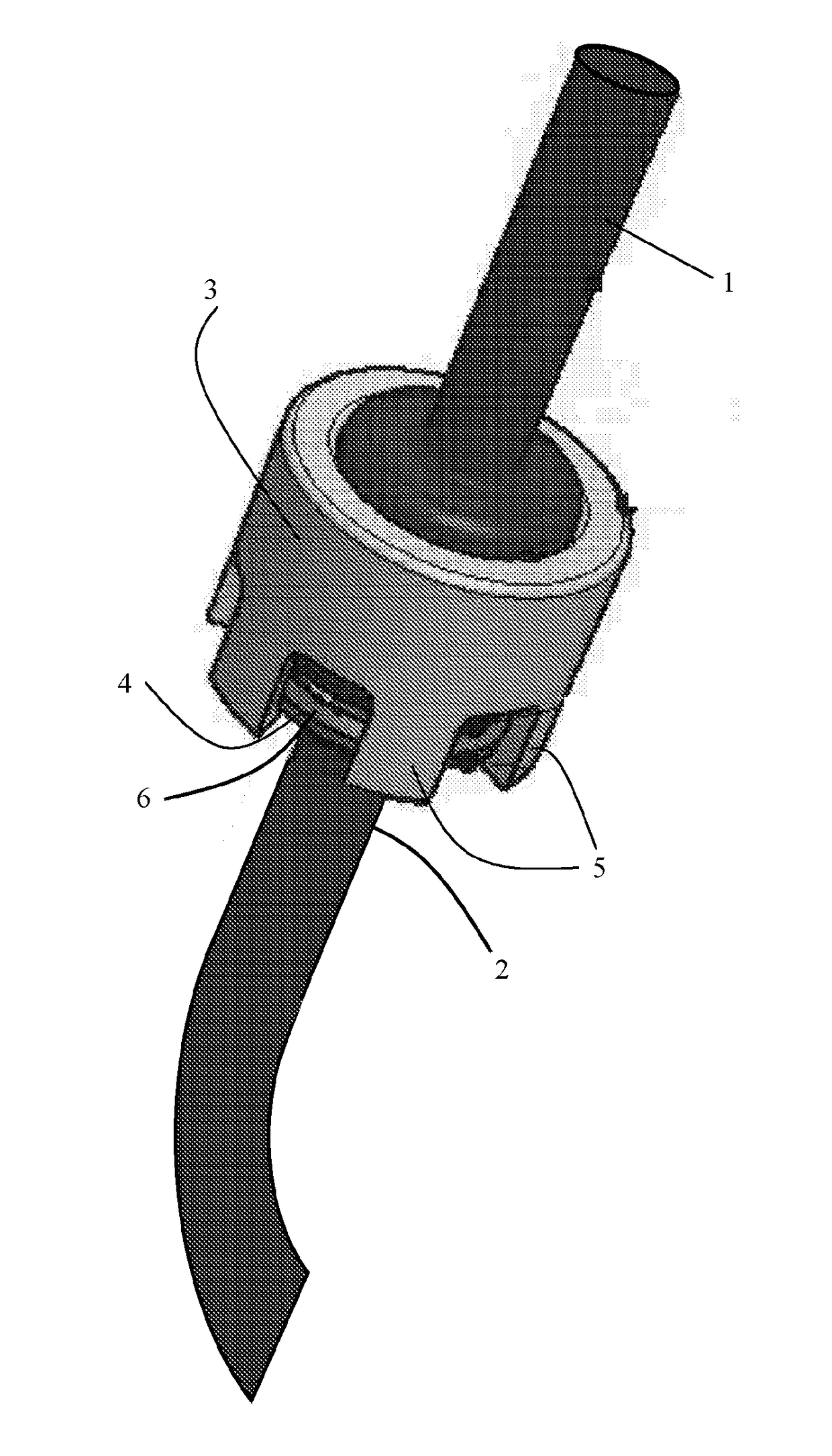
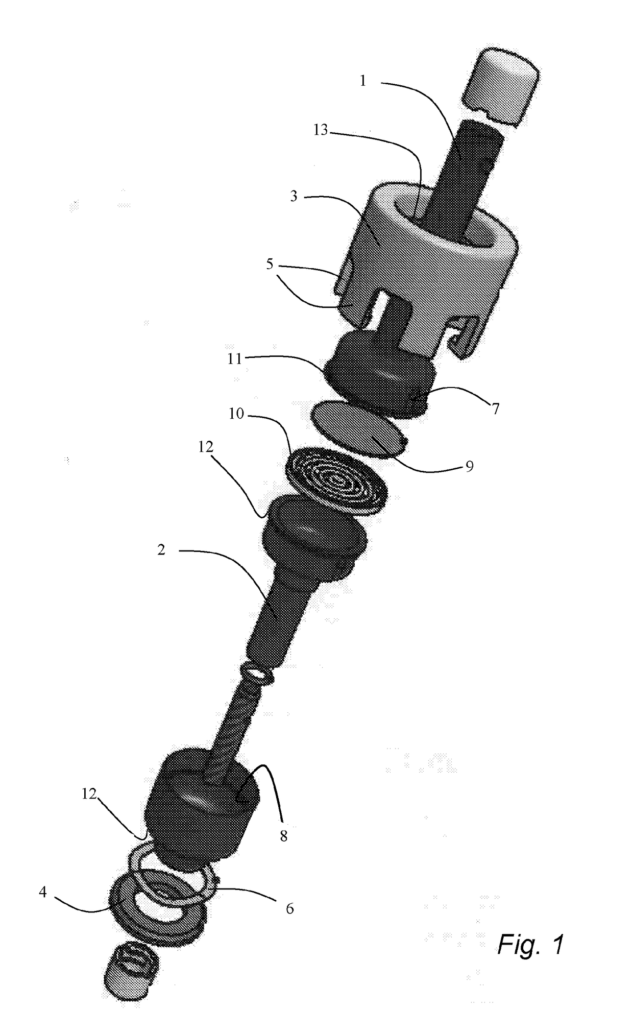
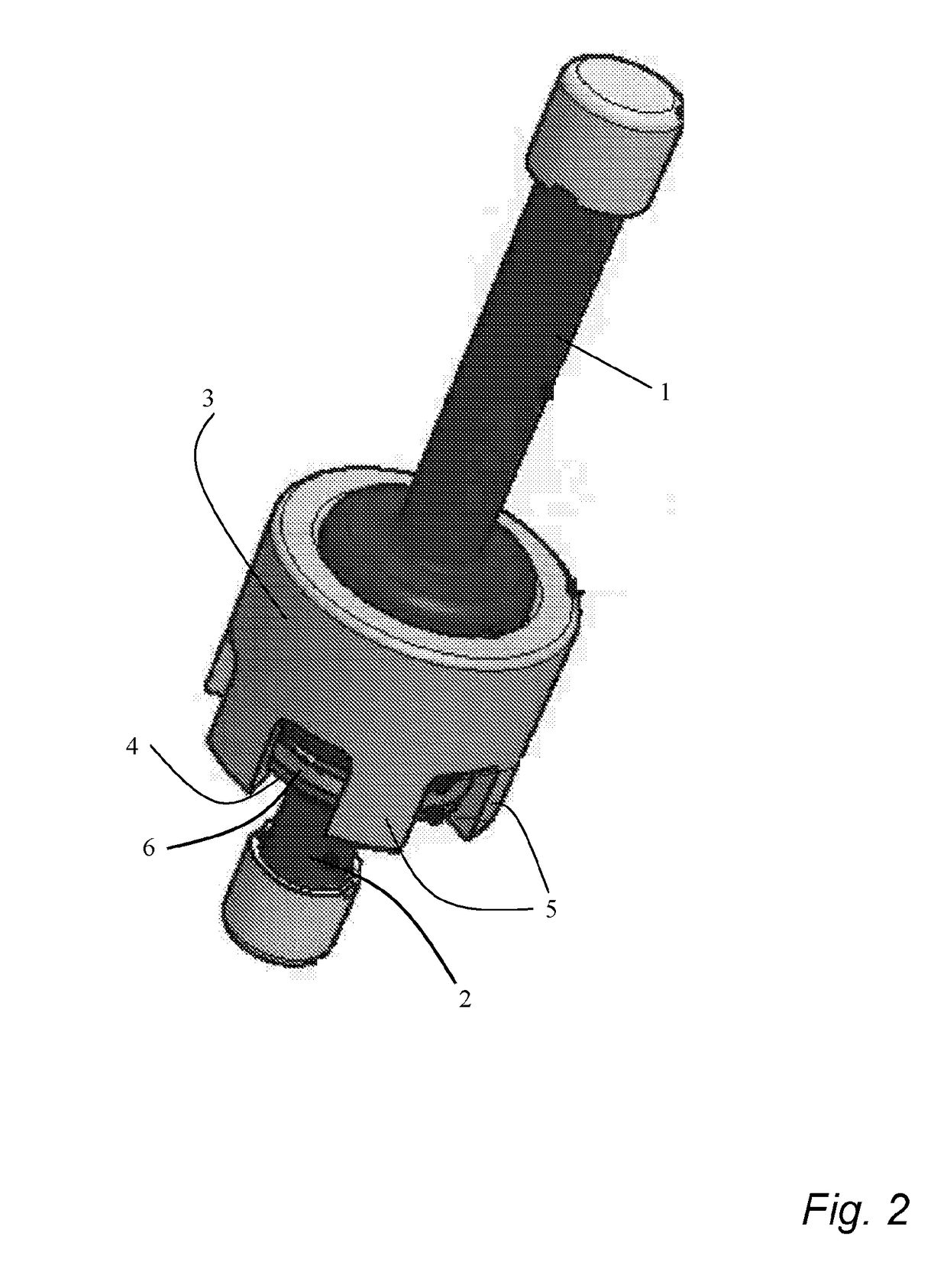
[0035]The present invention will now be disclosed more in detail with reference to FIG. 1, which shows a sealing connection assembly used for a sampling device. The first tubular part 1, the second tubular part 2, the filter device 9, and the filter holder 10 are pressed together in a fluid tight manner by the fi...


PUM

PropertyMeasurementUnit
forceaaaaaaaaaa
adsorptionaaaaaaaaaa
distancesaaaaaaaaaa

Abstract

A sealing connection assembly for fluid-tightly sealing of a first tubular part (1) to a second tubular part (2), wherein the sealing connection assembly comprises a first locking element (3) being adapted to at least partly enclose said first tubular part (1) and comprising at least one gripping element (5), a second locking element (4) being adapted to at least partly enclose said second tubular part (2). The sealing connection assembly is characterized in that said at least one gripping element (5) of said first locking element (3) is adapted to sealingly engage said second locking element (4) thereby locking said first tubular part (1) and said second tubular part (2) together, and in that said sealing connection assembly further comprises a resilient washer (6) arranged between said first locking element (3) and said second locking element (4), said resilient washer (6) being adapted to apply a force between said first locking element (3) and said second locking element (4) in an axial direction of the sealing connection assembly when locked together. To be published:

Description

FIELD OF THE INVENTION[0001]The present invention relates to a sealing connection assembly for fluid-tightly sealing of a first tubular part to a second tubular part. The invention further relates to a fluid-tightly sealable sampling device for environmental and medical analysis of one or more substances in a fluid flow intended to pass through the sampling device.BACKGROUND ART[0002]In many application areas it is important to facilitate a fluid-tight sealing between different parts as e.g. when connecting to pipes to each other, when connecting two hoses, when securing a lid to a container, etc. The quality of the sealing in the sense that it is reliably fluid-tight also for long periods of time, is especially important in laboratory environments or in medical environments, since leakage could lead to faulting measurements, damage to equipment or wrong dosage or contamination of drugs to a patient.[0003]One example is sealing, with a lid or cap, of a test tube for storing a gas or...

Claims


Application Information

Patent Timeline
Patent Type & Authority Applications(United States)
IPC IPC(8): B01L3/00G01N1/20F16L37/133A61M39/10G01N1/22
CPCB01L3/563A61M39/1011B01L3/502G01N1/2205F16L37/133F16L2201/44B01L2200/087B01L2200/0689B01L2200/026B01L2300/0681G01N1/20G01N2001/007F16L2201/40A61M2039/1027A61M39/26
Inventor SKARPING, GUNNARDALENE, MARIANNE
Owner PROVTAGAREN
Why Eureka
Try Eureka