
Fluid-tightly sealable sampling device

a sampling device and sealable technology, applied in the field of fluid-tight sealable sampling devices, can solve the problems of false positive results, high cost for users, and inability to identify individual chemicals, so as to reduce the risk of manipulation and reuse of sampling devices, the effect of increasing liability

Active Publication Date: 2020-04-28
PROVTAGAREN
View PDF28 Cites 0 Cited by
  • Summary
  • Abstract
  • Description
  • Claims
  • Application Information

AI Technical Summary

Benefits of technology

The present invention aims to solve the problems of leaks and poor sealing in sampling devices used for environmental, laboratory, and medical analysis. The invention provides a fluid-tightly sealable sampling device that improves the sampling process and reduces the risk of manipulation and reuse of the device.

Problems solved by technology

Non-selective devices give a response for several compounds and do not differentiate between two or several compounds and may also result in false positive results.
In many applications, false positive results can give rise to a high cost for the user, if costly measures are performed from invalid data.
For PID and FID, identification of the individual chemicals is not possible.
Infrared detectors suffer from problems with inferences.
IR detectors are not possible to use when monitoring VOCs at low concentration when other interfering compounds are present.
Exposure to this new type of isocyanates was previously unheard of.
Isocyanates have a varying degree of toxicity to the organism depending on their chemical and physical form.
Thermal decomposition products from PUR constitute a special problem, since new and completely unknown isocyanates are formed, whose toxicity has not yet been analyzed in a satisfactory manner.
Furthermore, the increasingly sophisticated measuring methods have revealed exposure to isocyanates in an increasing number of operations in industry.
If leakage occurs during the measurement in such a way that the gas flow may circumvent the filter, the measurement will be inaccurate.
Currently used samplers show some structural drawbacks.
By rotating either the filter holder or the adsorption tube, or both, when assembling the sampler components, the filter may be sheared or broken due to the rotational forces induced, and leaks may occur.
The filter may also unintentionally shift in position during the rotation of the sampler components creating large gaps around the filter, thereby making the measurement inaccurate.
A further problem is that when storing the assembled sampler, the pressure exerted on the filter may alter due to ageing of the filter.
Thereby the sealing properties may be negatively affected.
Otherwise, the measurements may be negatively affected and destroyed by the undesired diffusion into the sampler.
Thus, as sampling in several environments may be very expensive and require highly accurate measurement results, it is of great importance that the sampler is fluid-tight against the outside environment when assembled, in particular during handling and transport before and after the measurements.
A further problem in connection with the use of caps is that when they are removed and placed nearby the sampler during the measurements, they may adsorb substances on their surfaces.
When the caps are attached to the sampling device, the substances adsorbed on the surface of the inlet cap which is in contact with the interior of the sampling device may be desorbed and then instead be adsorbed in the adsorption tube, thereby disturbing the measurement result.
Correspondingly, substances adsorbed in the surface of the outlet cap which is in contact with the interior of the sampling device may be desorbed and instead then be adsorbed on the bottom surface of the filter, thereby also disturbing the measurement results.
Caps that are removed and placed nearby the sampler during measurements may also be lost, and it may also take time to find them after a finished measurement, allowing time for undesired diffusion into the adsorption device.
The latter is especially a problem in rough conditions, e.g. at measurements in cold places, where gloves are used, or at sea, where waves may make practical chores harder.
There is also a problem in connection with the use of sampling devices made by a standard polymer material or other no anti-static material in that air sampling through a non-conductive sampling device can create an electrical static charge to develop on the surfaces of the sampling device.
This creates incomplete recovery of the sample, since particles of interest are left behind in the sampling device, and these wouldn't be analyzed.
This problem creates an inaccurate concentration determination from the collected air sample.
Another problem in connection with use of sampling devices for the measurement of air-borne compounds in a fluid flow is the risk that the sampling device is tampered or manipulated during handling thereof, i.e. during the period from when it is transported from the supplier or the analysis laboratory to the user, is subjected to the sampling step by the user, and then is transported from the user to the analysis laboratory.
However, it has turned out that sampling devices have been manipulated or tampered with during the transports or by the user before, during, and after the sampling step, either unintentionally or intentionally.
This of course leads to false or inaccurate analysis results in the end.
Another problem is that when the sampling device has been used once it is further used one or more times after the analysis step of the laboratory.
When such a sampling device is sent to a user for sampling, the interior surfaces thereof normally are contaminated with different compounds from the previous sampling, and the analysis results finally obtained at the analysis laboratory will be false or inaccurate.

Method used


Image

  • Fluid-tightly sealable sampling device
  • Fluid-tightly sealable sampling device
  • Fluid-tightly sealable sampling device

Examples


Embodiment Construction

[0046]The expression “one or more substances” used throughout the application text means that two or more different substances in the fluid flow may be adsorbed by and react with one or more reagents at the same time within the sampling device. This is dependent on the choice of reagent or mixture of reagents present in the sampling device. In the following, the expressions “substance” and “substances” are sometimes used for simplicity reasons, but is nevertheless intended to mean “one or more substances”, unless otherwise is indicated or appears from the context.

[0047]The expression “one or more reagents” used throughout the application text is intended to mean that more than one type of reagent may be used when more than one type of substance in the fluid flow is to be analyzed. In the following, the expressions “reagent” or “reagents” are sometimes used for simplicity reasons, but is nevertheless intended to mean “one or more reagents”, unless otherwise is indicated or appears fr...


PUM

PropertyMeasurementUnit
inner diameteraaaaaaaaaa
lengthaaaaaaaaaa
pore diameteraaaaaaaaaa

Abstract

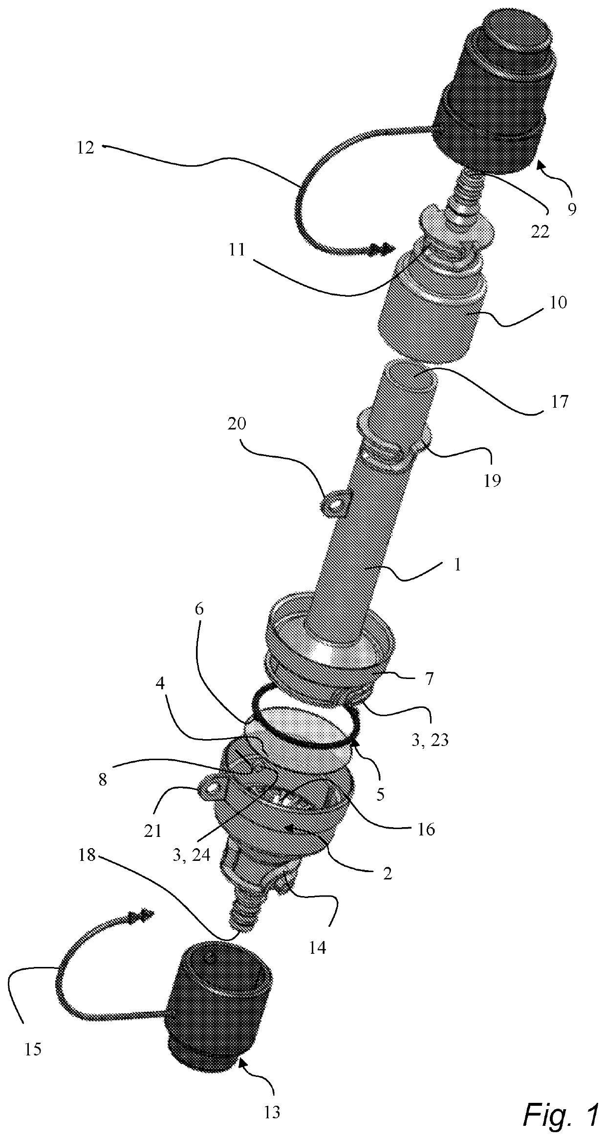
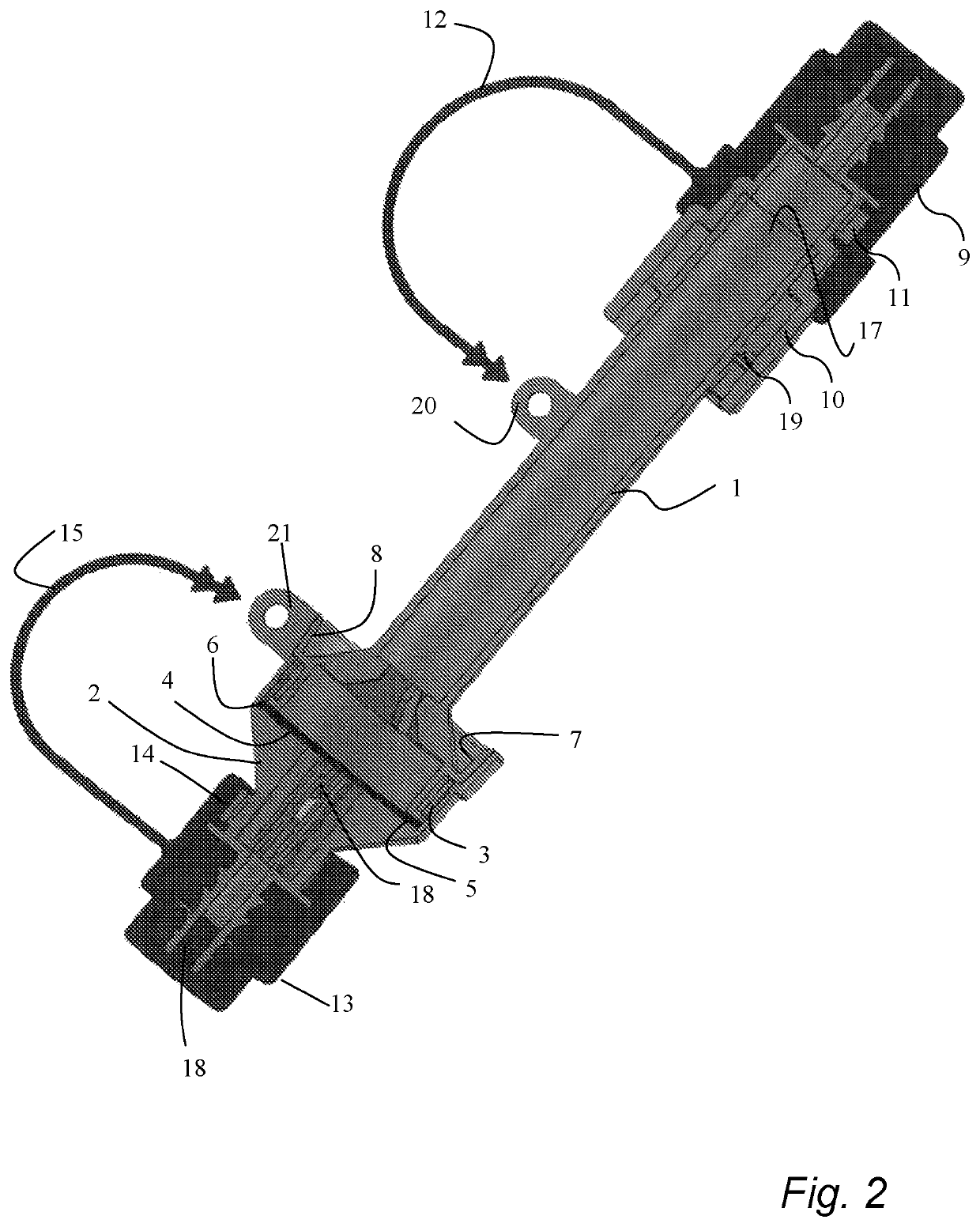
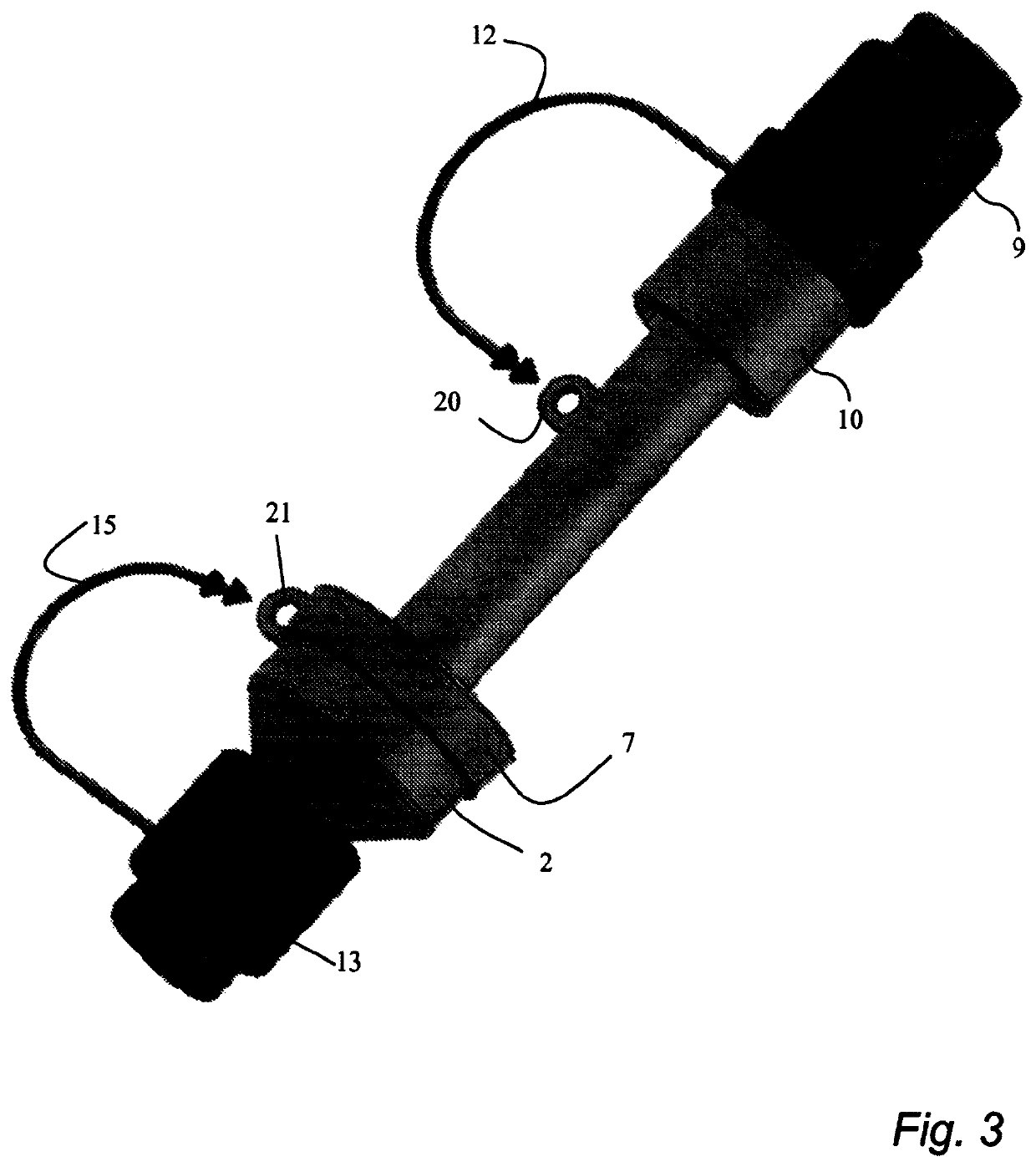
A fluid-tightly sealable sampling device for analysis of one or more substances in a fluid flow intended to pass through the sampling device is disclosed, wherein it comprises an adsorption device (1) which is hollow and is adapted to be provided with one or more reagents for adsorption of and reaction with said one or more substances in the fluid flow, a filter holder (2), which is hollow and is connected in a fluid-tight way with the adsorption device (1), a filter device (4) adapted to be provided with one or more reagents for adsorption of and reaction with said one or more substances in the fluid flow, a gasket (5) provided with at least one projection (6) engaged with at least one corresponding receiving slot in the filter holder (2), a first external cap (9) detachably connected with the inlet end of the sampling device in a fluid-tight way and a second external cap (13) detachably connected with the outlet end of the sampling device in a fluid-tight way.

Description

FIELD OF THE INVENTION[0001]The present invention relates to a fluid-tightly sealable sampling device for environmental and medical analysis of one or more substances in a fluid flow intended to pass through the sampling device.BACKGROUND ART[0002]There is a clear demand for the monitoring of air-borne compounds that may have health effects on exposed individuals. A great interest exists for compounds that have occupational exposure limit values, set by governmental bodies, to ensure that the levels of such compounds are satisfactory low. In many cases it is not known what the air contaminants consist, of and for this reason it is of interest to learn more details about the nature of these “unknown” compounds and to reveal the identity of the most predominate ones. Another field of interest is to study and check the effect of measures with a view to reducing these levels in air, e.g. to check the “true” ventilation efficiency or other measures to control the air levels. Devices for ...

Claims


Application Information

Patent Timeline
Patent Type & Authority Patents(United States)
IPC IPC(8): G01N33/538G01N1/20G01N1/14G01N1/22G01N1/40G01N33/537G01N33/543G01N1/00G01N1/02
CPCG01N1/14G01N1/20G01N33/5375G01N1/2205G01N33/538G01N1/405G01N33/5436G01N1/22G01N1/2214G01N1/2247G01N2001/022G01N2001/2223G01N2001/4088G01N2001/007
Inventor SKARPING, GUNNARDALENE, MARIANNE
Owner PROVTAGAREN
Learn More