Molding Tools and Method With Grip-Enhancing Structure

a technology of gripping structure and molding tools, which is applied in the field of molding tools and a method, can solve the problems of reducing the yield of the production process and increasing waste, and achieve the effects of increasing the gripping or holding of the edge portion, reducing or preventing the pullback or retraction of the cut edge, and reducing or preventing the pullback or retraction of the edg

Active Publication Date: 2017-07-06
SAM SUNGAN RALPH PAGENDARM GMBH
View PDF2 Cites 1 Cited by
  • Summary
  • Abstract
  • Description
  • Claims
  • Application Information

AI Technical Summary

Benefits of technology

[0007]In view of the above, it is an object of at least certain embodiments of the present invention to provide an apparatus and a method for forming a trim component in a manner whereby the slipping, shrinkage, pull-back or retraction of the edge of the trim component during the molding process thereof is reduced, minimized or entirely prevented. More particularly, it is an object of at least certain embodiments of the invention to form a cut edge of the trim component during the molding process, and also provide increased gripping or holding of an edge portion of the trim component during the molding process to reduce or prevent a pull-back or retraction of the cut edge during the molding process. Another object of at least certain embodiments of the invention is to ensure that at least the visible surface of the front face of the trim component is not damaged or visibly harmed in any way during the molding process while reducing or preventing pull-back or retraction of the edge. Further particularly, it is an object of at least certain embodiments of the invention to increase the gripping or holding of the edge portion of the trim component in the mold cavity during the molding process, and to hold-down the edge portion of the trim component during the molding process, in order to reduce or prevent the edge retraction. More generally, an object of at least certain embodiments of the present invention is to produce a molded trim component of which the edge at a perimeter thereof is fixed and maintained at the proper designed location thereof after the trim component is removed from the molding tools, so that the trim component edge has its nominal or designed position and shape on the finished trim component. A further object of at least certain embodiments of the invention is to reduce the amount of waste material by reducing the amount of excess material that would otherwise be required along the edge of the raw material layers to allow for shrinkage or pull-back retraction thereof during the molding process. The invention further aims to avoid or overcome the disadvantages of the prior art, and to achieve additional advantages, as apparent from the present specification. The attainment of these objects is, however, not a required limitation of the claimed invention.

Problems solved by technology

However, due to tolerances and misalignments that can arise during the laminating and molding process, and due to the stretching and three-dimensional molding deformation of the cover layer and the substrate during the molding process, the various layers of the trim component may stretch, shrink, retract or pull-back by differing extents at the edge of the trim component.
Such variable shrinkage, retraction or pull-back of the edge of one or more layers of the component is unacceptable and can lead to a finished trim component being rejected due to unacceptable edge quality, therefore leading to increased waste and lower yield of the production process.

Method used


Image

  • Molding Tools and Method With Grip-Enhancing Structure
  • Molding Tools and Method With Grip-Enhancing Structure
  • Molding Tools and Method With Grip-Enhancing Structure

Examples


Embodiment Construction

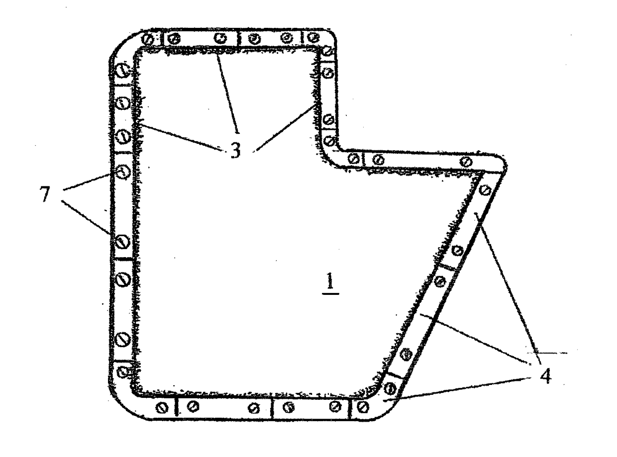
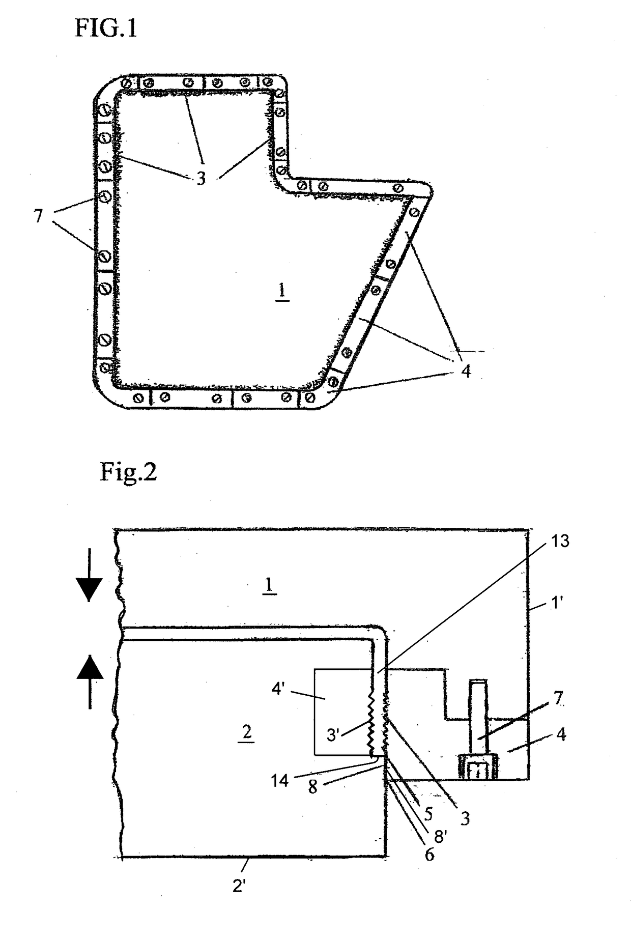
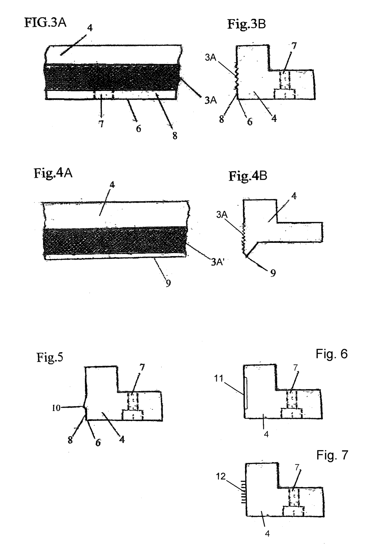
[0023]The drawings merely schematically illustrate a few components and only a small portion of an overall complete molding apparatus according to several different embodiments of the invention. Particularly, the drawings illustrate only portions of upper and lower mold tools. This limited schematic illustration is sufficient to enable a person of ordinary skill in the art to practice the invention, because other non-illustrated components and portions of such a molding apparatus are conventionally known or understood. For example, a person of ordinary skill readily understands that the molding apparatus includes additional components and devices that are not, and do not need to be, illustrated; such as heating devices, cooling devices, material carrying frames, material transport conveyors, actuators, controls, machine frames or supports, etc. Such additional devices and components can be embodied, configured and arranged in any conventionally known or understood manner. For exampl...


PUM

PropertyMeasurementUnit
moldingaaaaaaaaaa
surface roughnessaaaaaaaaaa
friction coefficientaaaaaaaaaa

Abstract

A molding apparatus includes two mold tools that define and bound a mold cavity therebetween, for three-dimensionally press-molding a trim component. To minimize or avoid shrinkage or pull-back recession of the edge of the trim component during the molding process, at least one of the mold tools, on its molding surface bounding an end portion of the mold cavity, includes at least one grip-enhancing structure that provides increased grip on an edge portion of the trim component. The grip-enhancing structure may be or include a rough surface, a geometric configured surface, a geometric gripping edge, a surface coating, or mechanical engagement members. The grip-enhancing structure provides increased grip on the edge portion of the trim component by narrowing the mold cavity space, by increasing the surface friction or adhesion, and/or by mechanically engaging the material of the trim component. Thereby, the edge of the trim component is held in place while the three-dimensional molding proceeds and until the molded contour of the component is fixed.

Description

FIELD OF THE INVENTION[0001]The invention relates to molding tools and a method for forming a molded trim component with reduced slippage, shrinkage, pull-back or retraction of an edge of the trim component material during the molding thereof.PRIORITY CLAIM[0002]This application is based on and claims the foreign priority under 35 USC 119 of German Utility Model Application DE 20 2016 000 052.8 filed on Jan. 6, 2016, the entire disclosure of which is incorporated herein by reference.BACKGROUND INFORMATION[0003]Trim components such as trim panels are typically used for covering and finishing the interior passenger cabins of automobiles, aircraft, rail vehicles, etc. as well as luggage areas and some external areas of such vehicles. For example, in automotive applications such trim components include headliners, door liners, armrest pads, storage bins, consoles, dashboard covers, load floors, package trays, pillar covers, trunk liners, carpeted floor liners, engine hood covers, wheel ...

Claims


Application Information

Patent Timeline
Patent Type & Authority Applications(United States)
IPC IPC(8): B29C43/36
CPCB29L2031/3041B29C43/36B30B15/02B30B15/08
Inventor VAN DER LINDE, ALBERT
Owner SAM SUNGAN RALPH PAGENDARM GMBH
Why Eureka
Try Eureka