Device that uses gravity to move weights across a shaft assembly for rotation and torque and a braking apparatus to regulate rotation speed

Inactive Publication Date: 2017-07-06
SEQUEIRA ANTHONY E
View PDF5 Cites 11 Cited by
  • Summary
  • Abstract
  • Description
  • Claims
  • Application Information

AI Technical Summary

Benefits of technology

[0004]Generally, the apparatus described in the preferred embodiments, along with the illustrations, provides a unique device which uses gravity to move weights

Problems solved by technology

These devices, however,

Method used


Image

  • Device that uses gravity to move weights across a shaft assembly for rotation and torque and a braking apparatus to regulate rotation speed
  • Device that uses gravity to move weights across a shaft assembly for rotation and torque and a braking apparatus to regulate rotation speed
  • Device that uses gravity to move weights across a shaft assembly for rotation and torque and a braking apparatus to regulate rotation speed

Examples


Embodiment Construction

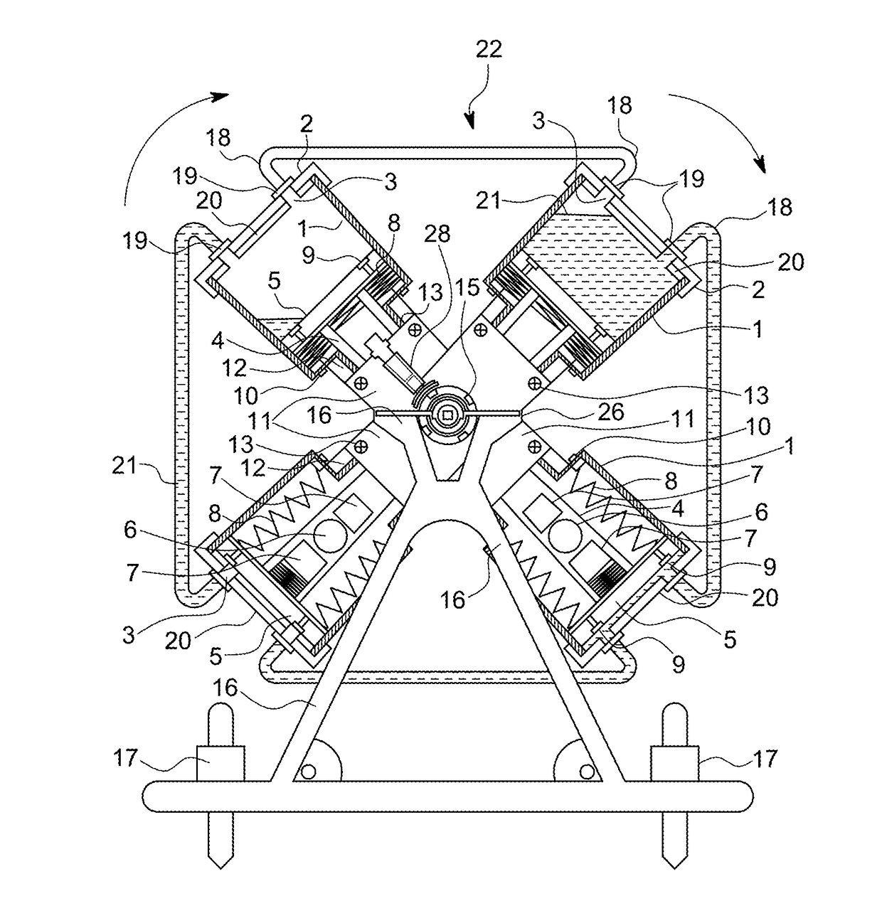
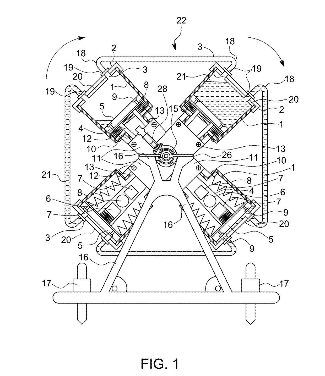
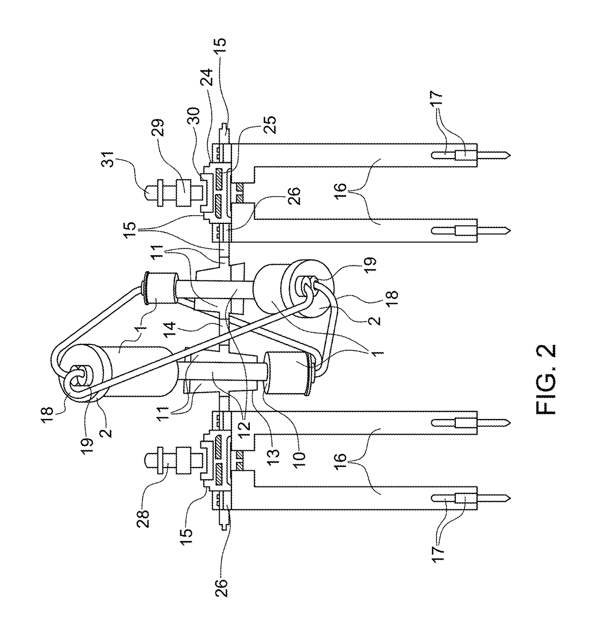
[0071]This application describes a device that uses gravity to move weights across a configured Shaft Assembly for generating rotation and torque, the speed regulated by a gravity driven braking mechanism, is described herein, together with the drawings and illustrations in FIG. 1 to FIG. 15 and described generally by the reference numeral 22.

[0072]In a preferred embodiment, the device 22 includes one or preferably a plurality of Oblong Cylindrical Containers 1 having narrow mid-section and larger liquid Chambers at each of the two ends, each Chamber with Caps 2 having threaded dual Nozzles 3. Each Oblong Cylindrical Container 1 encases a Piston comprising a tube 4 of length equal to the mid-section of the Oblong Cylindrical Container 1 plus height of a collapsed Bellow 8, with Cap-Heads 5 at both ends. Within each Piston may be a Solid Heavy Density Matter 6 or other Matter and having optional two blocks of Solid Light Weight Matter called “Stoppers”7 on either side of the Solid He...


PUM


Abstract

A rotation generation device is provided that includes: at least one pair of Cylindrical Containers having Chambers therein at each end to receive and discharge a fluid, the Cylindrical Containers interconnected via a tubular member and mounted essentially perpendicular to a Shaft; Threaded Caps with dual nozzles that screw on to each Chamber at the end of the Cylindrical Containers; two or more Pistons, each Piston interconnected to another Piston via a hollow tube, each Piston resides in a sliding relationship in a respective Cylindrical Container and wherein the hollow tube resides in the tubular member, the hollow tube having a length for a first of the two or more pistons to cause one of the Cylindrical Containers to receive fluid as the first piston slides within the respective Cylindrical Container, while a second of the two or more pistons causes another of the Cylindrical Containers to discharge fluid therein; a weight, residing and capable of moving laterally within the hollow tube; Pipes interconnecting adjacent Cylindrical Containers via the Cap nozzles; bellows within each Chamber of the Cylindrical Containers, wherein each bellow attaches on one end to a Piston and at an opposite end to the Chamber of the Cylindrical Container.

Description

RELATED APPLICATION[0001]This application claims the benefit of U.S. Provisional Application No. 62 / 271,645, filed Dec. 28, 2015, which is hereby incorporated herein by reference.BACKGROUND[0002]The present application relates to rotation and torque generating devices, and more particularly gravity assisted generation devices.[0003]Rotation generating devices are known, such as those disclosed in U.S. Pat. No. 29,149 to Durham, U.S. Pat. No. 3,034,964 to Diamond, U.S. Pat. No. 3,412,482 to Kusmer, U.S. Pat. No. 6,115,950 to Al-Mutairi, 4,363,212 to Everett, U.S. Pat. No. 5,372,474 to Miller, U.S. Pat. No. 5,944,480 to Forrest, U.S. Pat. No. 5,996,344 to Frenette et. al., U.S. Pat. No. 4,498,294 to Everett, U.S. Pat. No. 6,000,707 to Alkhamis, U.S. Pat. No. 4,254,622 to Denson, Sr, U.S. Pat. No. 4,407,130 to Jackson, U.S. Pat. No. 6,353,270 to Sen, and U.S. Pat. No. 6,764,275 to Carr. These devices, however, have their limitations. Accordingly, there is a need for a novel improvement...

Claims


Application Information

Patent Timeline
IPC IPC(8): F03G3/00F16D49/16H02K7/18F16D65/06
CPCF03G3/00F16D65/065F03G7/10H02K7/1807F03B17/005F16D49/16F16D49/00F16D65/06F03G7/107
Inventor SEQUEIRA, ANTHONY E.
Owner SEQUEIRA ANTHONY E
Why Eureka
Try Eureka