

Partial discharge signal processing device
- Summary
- Abstract
- Description
- Claims
- Application Information
AI Technical Summary
Benefits of technology
Problems solved by technology
Method used
Image

Examples
embodiment 1
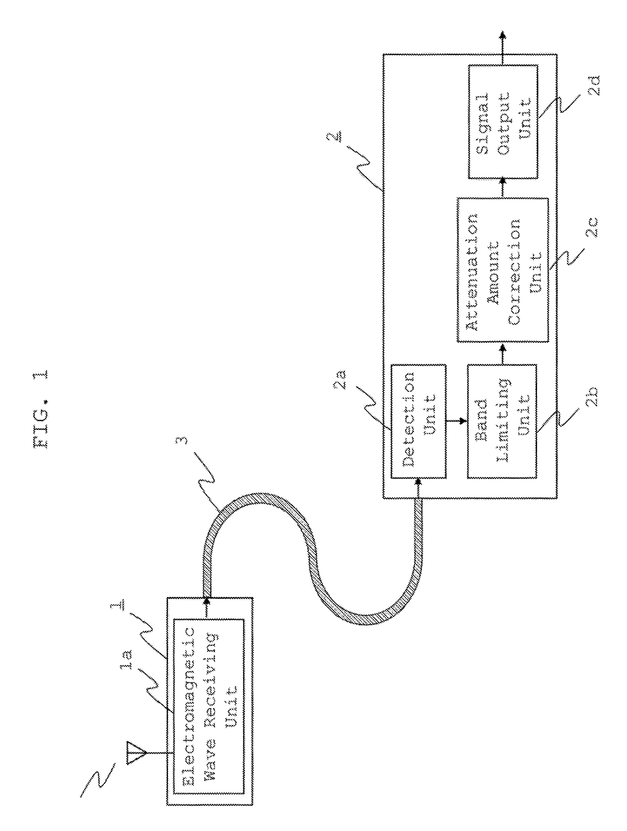
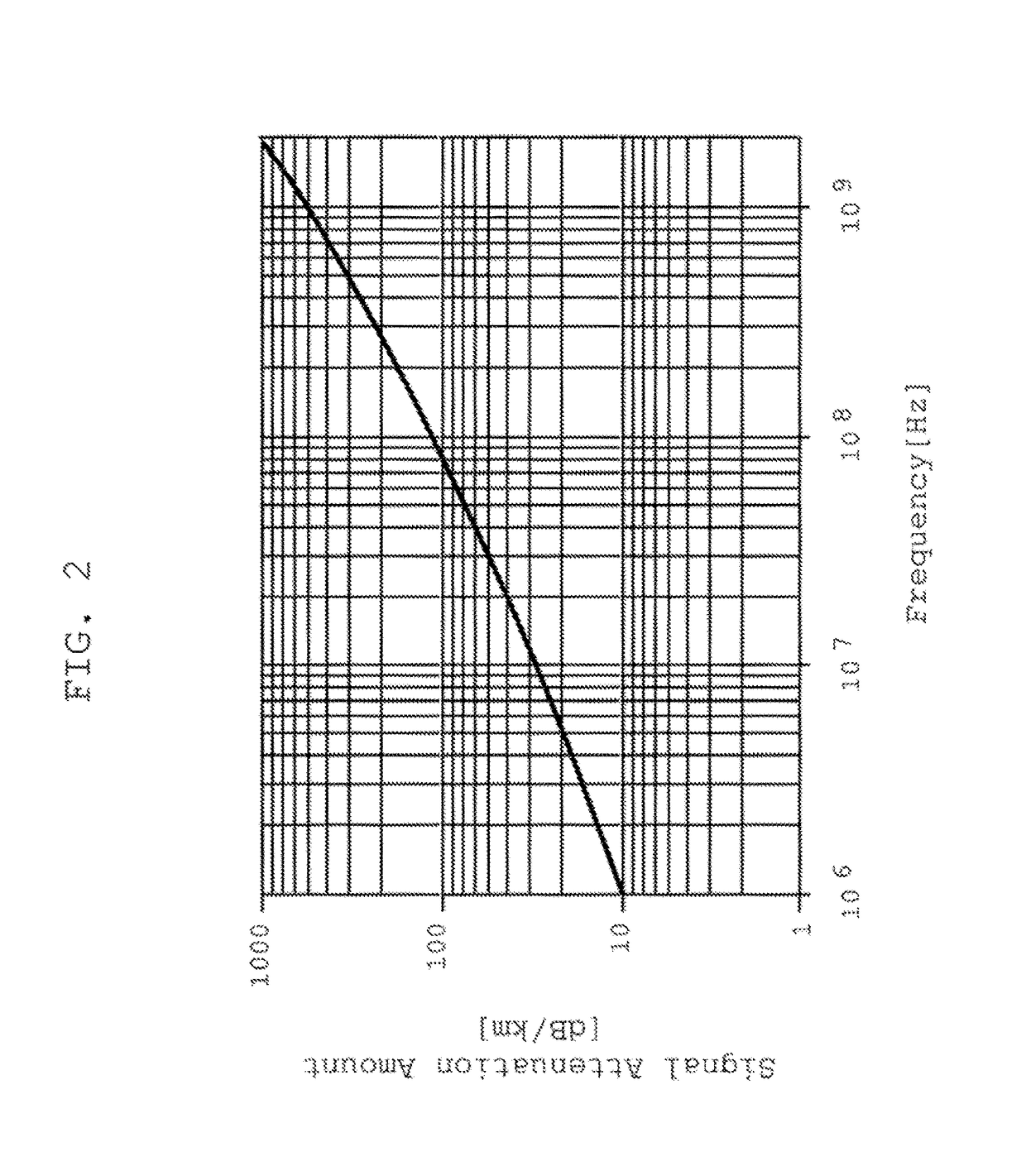
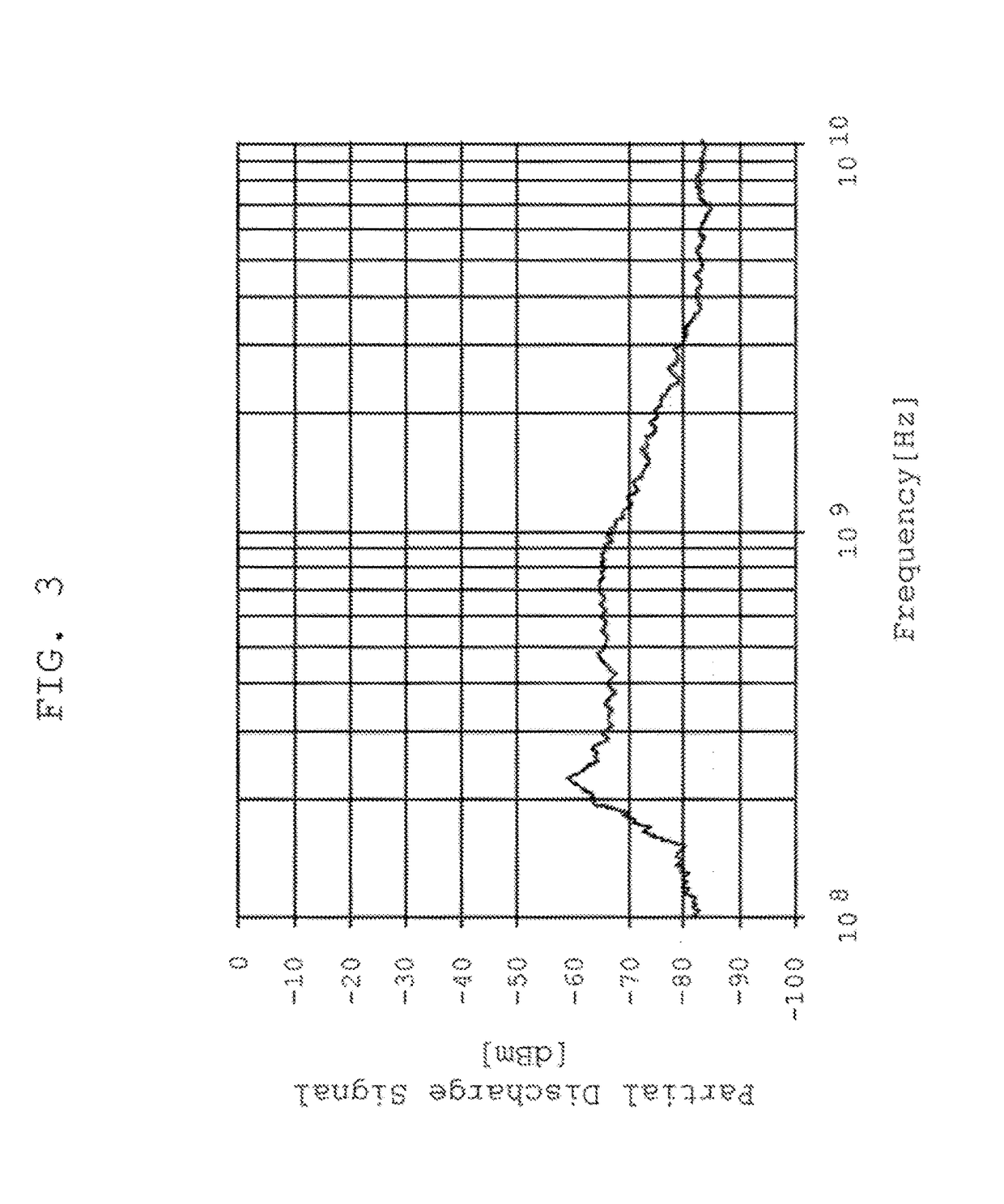
[0025]FIG. 1 is a view showing the schematic configuration of a partial discharge signal processing device according to Embodiment 1; FIG. 2 is a view showing an example of the signal attenuation characteristics of a coaxial cable; FIG. 3 is a view showing an example of the frequency characteristics of an electromagnetic wave caused by partial discharge; and FIG. 4 is a view showing a reference frequency and a bandwidth which are used for partial discharge signal processing.
[0026]First, the configuration of the partial discharge signal processing device according to Embodiment 1 will be described by using FIG. 1. In FIG. 1, the partial discharge signal processing device is composed of three segments: a partial discharge signal receiving unit 1 that is placed inside or outside a high voltage electric machine; a partial discharge signal processing unit 2 that is provided outside the high voltage electric machine; and a coaxial cable 3 serving as a transmission line through which the p...
embodiment 2
[0040]FIG. 5 is a view showing the schematic configuration of a partial discharge signal processing device according to Embodiment 2; and FIG. 6 is a view showing an example of the frequency characteristics of a signal amplifier. A difference from the partial discharge signal processing device according to Embodiment 1 shown in FIG. 1 is that, in a partial discharge signal processing device according to Embodiment 2, a signal amplification unit that amplifies the partial discharge signal by the amplification ratio corresponding to the attenuation amount in a coaxial cable is served as the attenuation amount correction unit. Other constitutional elements are the same as that of Embodiment 1 and therefore their description will be omitted.
[0041]Next, the operation of the partial discharge signal processing device according to Embodiment 2 will be described with reference to FIG. 5 and FIG. 6.
[0042]In Embodiment 2, in order to correct the attenuation amount of a coaxial cable 3, as the...
embodiment 3
[0045]FIG. 7 is a view showing the schematic configuration of a partial discharge signal processing device according to Embodiment 3. In the partial discharge signal processing device according to Embodiment 3, a plurality of partial discharge signal receiving units for receiving an electromagnetic wave generated by partial discharge and a plurality of partial discharge signal processing units are prepared and are provided at plural places in a high voltage electric machine; and ether constitutional elements are the same as those of Embodiment 1 and therefore their description will be omitted.
[0046]Next, the operation of the partial discharge signal processing device according to Embodiment 3 will be described with reference to FIG. 7.
[0047]A plurality of partial discharge signal receiving units 1, 10 (FIG. 7 shows a case where two partial discharge signal receiving units are provided.) are mounted at different places in the high voltage electric machine; an electromagnetic wave rec...
PUM
 Abstract
Description
Claims
Application Information