Intra Dermal Tissue Fixation Device

a tissue fixation device and dermal tissue technology, applied in the field of intra dermal tissue fixation devices, can solve the problems of taking a surgeon a long time to close with sutures, time-consuming, and insufficient strength or support of the deep dermal layers while the wound is healing

Active Publication Date: 2017-07-13
ETHICON INC
View PDF5 Cites 179 Cited by
  • Summary
  • Abstract
  • Description
  • Claims
  • Application Information

AI Technical Summary

Benefits of technology

[0022]Yet another aspect of the present invention is a tissue fastener. The tissue fastener has an elongated central member having a proximal end and a distal end and opposed lateral sides. A plurality of frictional engagement elements extend outwardly from each lateral side such that the engagement members on a first lateral side are opposed to the engagement members extending outwardly from the other lateral side. Each engagement member has a proximal end and a distal end and a cross-sectional area. Each engagement member additionally has a distal tip extending from the distal end, wherein the tip has a cross-sectional area that is smaller than the cross-sectional area of the engagement member.

Problems solved by technology

While it is important to maintain the edges of the epidermis in close alignment and approximation, the closure of the epidermis alone will not provide sufficient strength or support to the deep dermal layers while the wound is healing.
Relatively large incisions in excess of many centimeters may be made in the course of a surgical procedure which can often take the surgeon a very long time to close with sutures.
Not only is it time consuming, but surgeons often view the process as tedious.
Moreover, the repeated movement of the needle through the skin of the patient necessarily increases the risk to the surgeon or assistant of being exposed to a needle prick which in turn can lead to certain transmissions of infectious diseases including, but not limited to, Hepatitis C and HIV.
Foremost among the drawbacks associated with surgical skin stapling is the significant scarring associated with the presence of the staples during healing.
The presence of the transdermal portions of the staples, the leg elements, during healing, will produce a delayed region of healing that subsequently fills in with scar tissue.
If the staples are left in place too long there is the potential for the formation of sinus tracks around the transdermal elements.
Moreover, staples are significantly more painful to the patient in that they need to be removed after being installed and after the incision is healed.
This product (referred to as the AutoSuture SQS 20) was believed to be not successful for various reasons, including wound-healing problems which resulted from the undulating / interdigitating wound edge configuration.
The absorbable dermal stapling technology is believed to provide less than optimal horizontal and vertical alignment.
The presence of the stapling head within the wound may also present an additional interference at the end of the partially approximated wound.
Additionally, the method in which the fasteners hold the wound edges in eversion may result in prominent “dimpling” or “mounding” of the skin where the fasteners secure the skin edges, a closure appearance which can cause concern to surgeons when they use dermal staplers for wound closure.
While the '824 application attempts to position the first and second sections of skin relative to one another, the use of such an H-shaped anchor does not adequately pull the two sections close together after insertion and thus would result in longer healing times and more scarring than is acceptable.
Once it is so deployed and released, the anchor is pulled back by the opposite prong and the normal tension on the wound edges, thus resulting in slack in the anchor and a loose “seam”.
This action of the tissue engagement pulls the tissue edges together, however, as the hook like elements are rotating about an axis located below the tissues to be approximated, it is likely to cause in inversion of the epidermal layer as opposed to the desired eversion.
Further, the presence of the deployment head within the wound may also present an additional interference at the end of the partially approximated wound.
A deficit of this method of apposition is similar to the limitations of the '857 and '824 devices, this method of apposition also requires the use of gathering features to attempt to overcome the wedging or separating effect induced by the presence of the stapler head within the region to be joined.
Further, the presence of the deployment head within the wound may also present an additional interference at the end of the partially approximated wound.
Appropriate tensioning and continued engagement of the tissue in the presence of the inflammatory response of ordinary tissue healing may cause necrosis and subsequent dehiscence.
As such, the tissue can move away from the penetrator during rotation and result in misaligned tissue edges.
Additionally, the device is intended to be utilized within the margins of the wound and thus would suffer from the same wedging effect as detailed for the other devices offering an inter-wound deployment device.

Method used


Image

  • Intra Dermal Tissue Fixation Device
  • Intra Dermal Tissue Fixation Device
  • Intra Dermal Tissue Fixation Device

Examples


embodiment 200

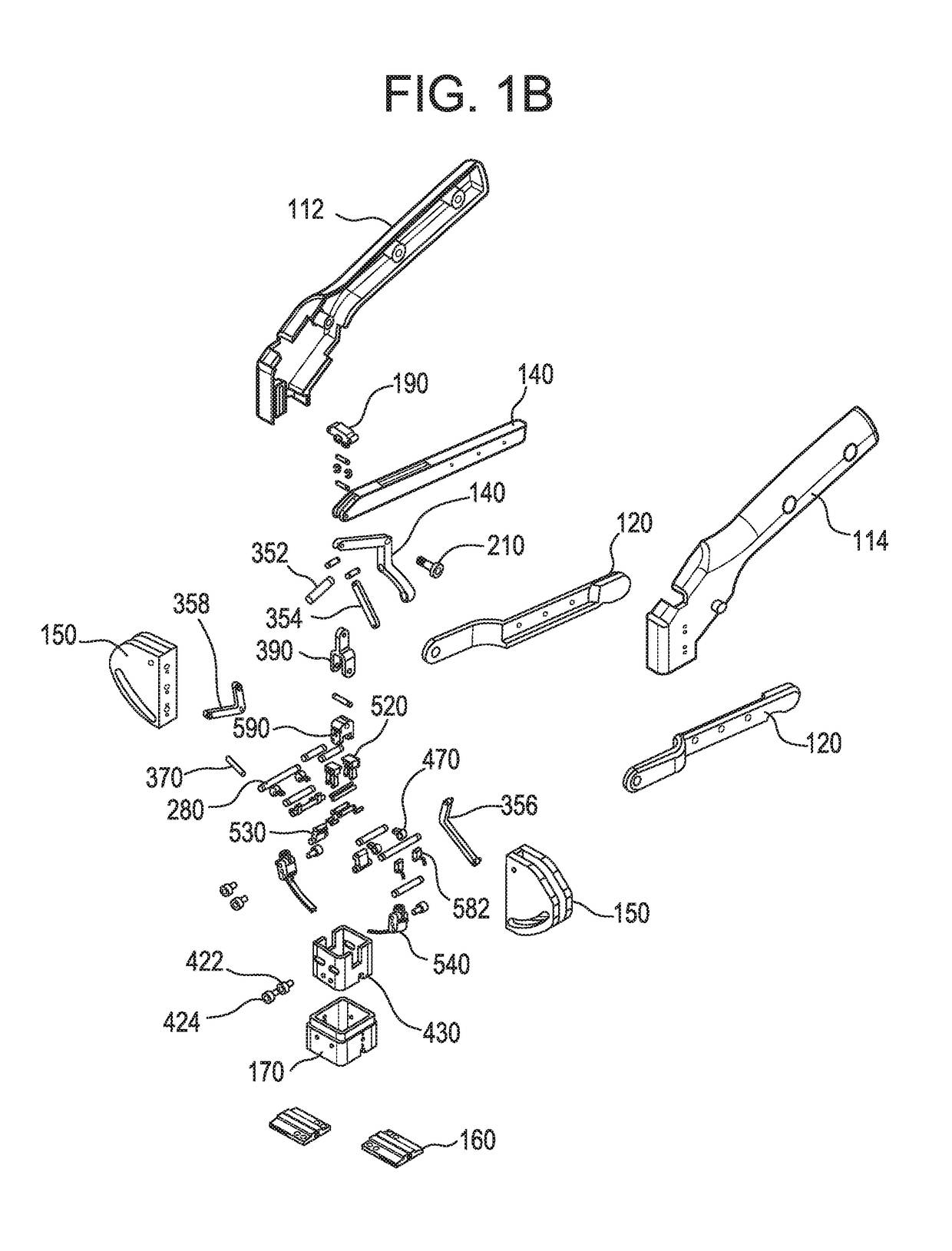
[0054]Referring to FIG. 3, the partially disassembled version 300 of the embodiment 200 of FIG. 2 is illustrated without one of the driver cam guides 150 and opposing wall support structures 262 and 264 to enable the visualization of the components typically assembled within this feature. The slot 350 in the distal end of the firing trigger 140 is shown. The slot 350 enables the slidable linkage with the center portion of the driver saddle element 190. The two lateral ends of the upper portion of the driver saddle are in pivotable engagement with two linkage bars 352 and 354. The two linkage bars 352 and 354 are in pivotable engagement with the upper ends of the acute link elements, 356 and 358. Additionally, the distal end 310 of the tissue engagement trigger slotted support bar is in pivotable engagement with the upper portion 394 of the driver yoke 390. The lower portion of the driver yoke 392 is formed in the shape of a “Y” to receive its mating component. The tissue fastener 37...

embodiment 300

[0055]Referring to FIG. 4, a partially disassembled version 400 of the embodiment 300 illustrated in FIG. 3 is provided. The axle housing is not present and the inner retractor housing 430 is shown. The device 400 includes four retractor housing cam levers 470, only one is labeled. The cam levers 470 are pivotably engaged to retractor housing through the location within the retractor housing slots 440. The opposite ends of the cam levers are pivotably engaged with their respective mating components. The retractor housing is produced with two opposed slots one of which is labeled 410. The slots 410 provide the necessary clearance to enable the retractor housing to be slidable vertically within the mating axle housing 170 element. The lower end of the acute linkage element 356 is in pivotable engagement with the stylus mount 420. The stylus mount 420 has two cam glide bearings 422 and 424 mounted to the opposite sides of the stylus mount 420. It can be seen that the cam glide bearings...

embodiment 400

[0056]Referring now to FIG. 5, a partially disassembled version 500 of the embodiment 400 detailed in FIG. 4 is provided. The balance of the linkage attachments will be detailed. The driver yoke is attached to the pivot base 590. The upper ends of four cam linkage bars 520 are pivotably attached to the pivot base 590 through the use of pins that are passed through the first pair of cam linkage bars 520 through the pivot base unit and through the second pair of cam linkage bars 520. The pins are longer than the width of the two pairs of cam linkage bars 320 and the pivot base unit. The extended ends of the pins are passed into pockets in the two opposing pivot base cap plates 510 that are fixedly attached to the pivot base. The opposite ends of the cam linkage bars 320 are pivotably attached to the cam lever extensions 594. The device is seen to have four tissue hook base elements 580. The tissue hook base element 580 is produced in an “L” shaped configuration. The thickest portion o...


PUM


Abstract

A device is disclosed for the securement of dermal tissues. The device provides approximation and eversion of the tissue as well as the placement of a fixation element that bridges a wound. The fixation element may be produced in several fixed or dynamic configurations that may or may not alter the ability to engage tissue in response to stresses placed upon the fixation member post-deployment. The delivery device inserts the fastener percutaneously through the epidermis into the sub-dermal position without entering the wound margins with any part of the approximation portion of the delivery device.

Description

FIELD OF THE INVENTION[0001]The field of art to which this invention pertains is medical devices for tissue fixation, more particularly devices for applying tissue fixation implants.BACKGROUND OF THE INVENTION[0002]Biological healing of a tissue opening such as a wound commences through the proximity of the opposed wounded surfaces of living tissue. If the opening is very large or if its location subjects the wound to continual movement, forcibly holding the sides of the opening in close proximity will promote the healing process.[0003]Human skin tissue is comprised of three distinct layers of tissue. The epidermal layer, also known as the epidermis, is the outermost layer and includes non-living tissue cells. The dermal layer, or dermis, is the middle layer directly below the epidermal layer and comprises the living tissue of the skin that is the strongest of the three layers. The subcutaneous, or hypodermis layer is the bottom layer of skin tissue and includes less connective tiss...

Claims


Application Information

Patent Timeline
Patent Type & Authority Applications(United States)
IPC IPC(8): A61B17/068A61B17/08
CPCA61B17/068A61B2017/00004A61B2017/081A61B17/08A61B17/0482A61B17/064A61B2017/00349A61B2017/0472A61B2017/06042A61B2017/06176A61B2017/0647A61B2090/08021
Inventor ROUSSEAU, ROBERT A.LINDH, SR., DAVID C.
Owner ETHICON INC
Why Eureka
Try Eureka