
Button Anchor System for Moving Tissue

a button anchor and moving tissue technology, applied in the field of button anchor systems for moving tissue, can solve the problems of poor force distribution across the tissue, lack of practical means for adjusting the force exerted by the suture, and poor rudimentary coupling work, etc., to achieve the effect of restoring and moving tissues, simple, and cost-effectiv

Inactive Publication Date: 2011-06-09
CANICA DESIGN
View PDF99 Cites 8 Cited by
  • Summary
  • Abstract
  • Description
  • Claims
  • Application Information

AI Technical Summary

Benefits of technology

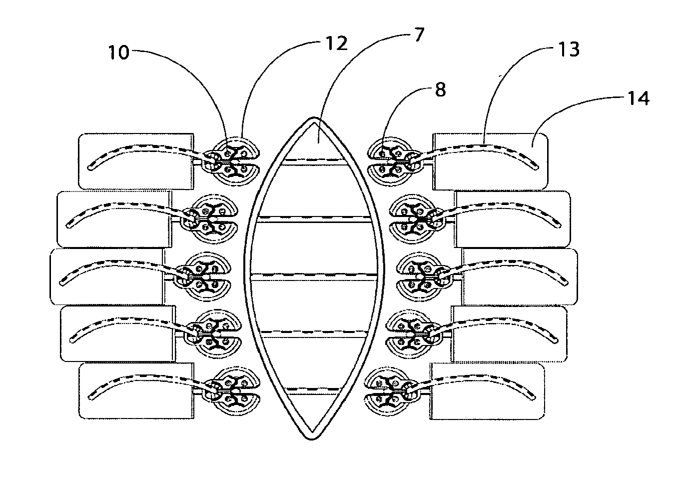
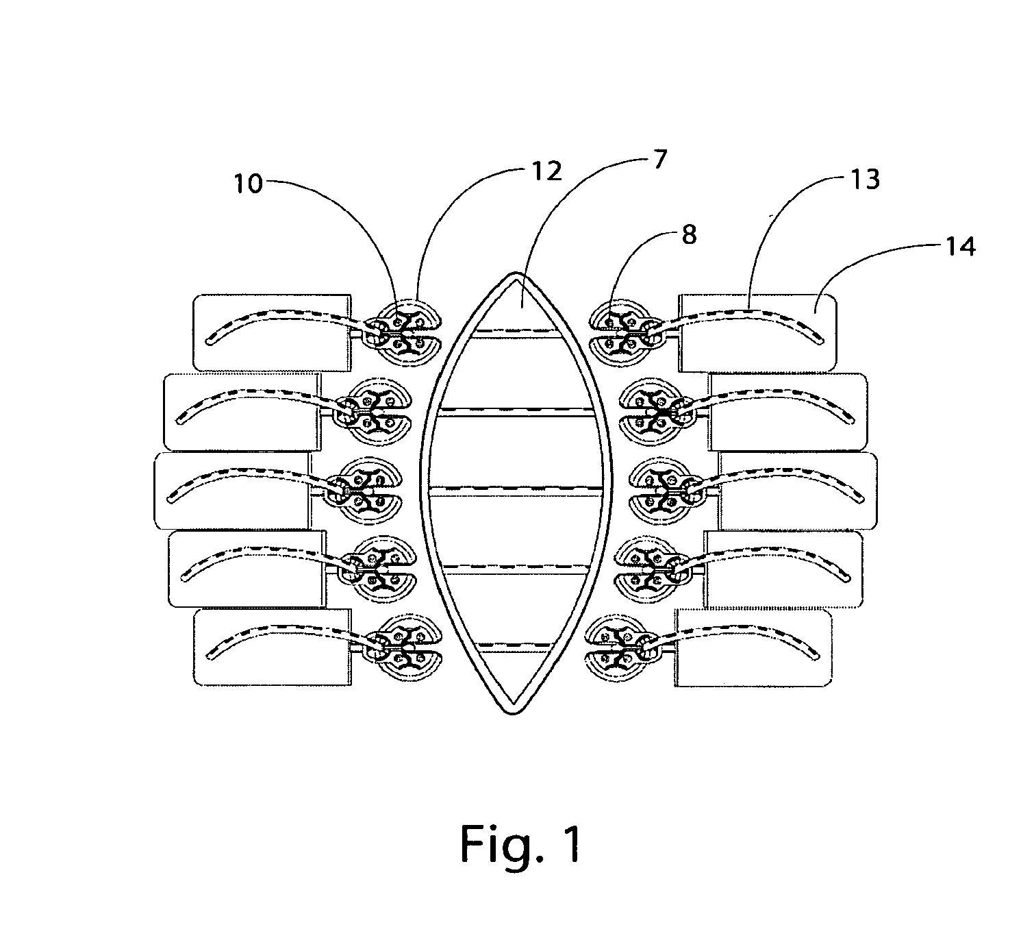
"This patent describes a new invention that allows for the manipulation and control of tissue positions and tensions on a living person or animal. It uses both tissue stretch and creep to restore and move tissues, providing a simple and effective way to move plastic tissue. The invention exerts a dynamic force on the tissue, creating a maximum safe counter-traction pressure or force across a wound margin or other area. It can be used to close dermal wounds, incisions, or defects that may be associated with a variety of conditions, as well as in the stretching of healthy skin in preparation for a skin graft, flap, or other remodeling procedure. The invention is self-adjusting and capable of exerting relatively constant force or tension over a variety of distances and at various intersecting angles in wounds having simple or complex geometry. It provides a means for quick and easy attachment and reattachment of various facs, particularly including facs made of silicone, and allows for expansion and contraction of the wound site, which greatly enhances patient mobility and is compliant with respiratory movements. Overall, this invention offers the advantage of a relentless countertraction force and provides a more effective and efficient way to move and stretch tissue."

Problems solved by technology

However, such rudimentary coupling works poorly for several reasons, importantly including the extremely poor force distribution across the tissue and the absence of any practical means for adjusting the force exerted by the suture over a period of time.

Method used


Image

  • Button Anchor System for Moving Tissue
  • Button Anchor System for Moving Tissue
  • Button Anchor System for Moving Tissue

Examples


Embodiment Construction

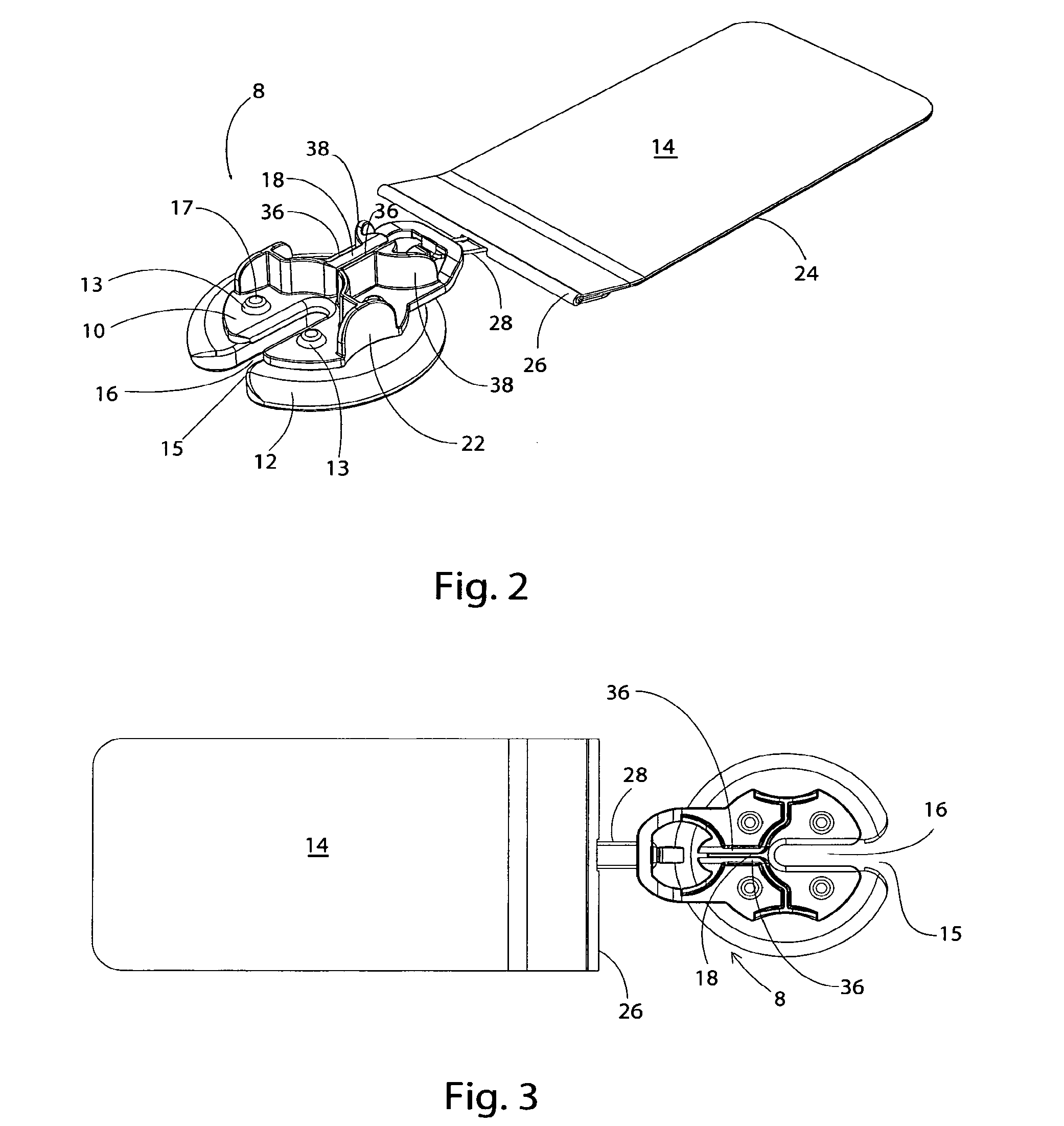
[0032]Anchors of this invention are used to transmit and distribute force to the tissue to be moved or stretched. A force applying component according to this invention may be formed in rods, cords, bands, loops, sheets, nets, wires, strands, cables, tubes or other suitable structure. In one embodiment, the fac is an elastic strand that flattens out at the point of maximum load and becomes load dissipating. In one embodiment, a rod-shaped fac is driven through the tissue using a cannula-like device and is attached at each end to an anchor.

[0033]Force applying components (“facs”) of this invention may have elastic properties “efacs”) and may be made from any suitable elastomeric material, including, without limitation, latex rubber, silicone, natural rubber and materials of similar elasticity, GR-S, neoprene, nitrile-butyl-polysulfide, ethylene-polyurethane, polyurethane, or any other suitable material that exhibits the property of exerting a return force when held in an elongated st...


PUM


Abstract

A system of non-reactive components for moving or for moving and stretching plastic tissue that exerts a relatively constant dynamic force over a variety of distances and geometries, that is easily adjustable, and is self-adjusting. This system includes a “button anchor system” for moving tissue, particularly including deep fascia and muscle layers of the abdominal or thoracic cavity wall, in surgical, post surgical, and post traumatic reconstruction where the wound margins are beyond a distance that permits normal re-approximation. Button anchor assemblies allow re-approximation of severely retracted abdominal wall and full thickness thoracic wounds where a closure force is required to be applied to the sub-dermal layers. Systems of this invention allow for such a force to be applied and externally controlled during treatment.

Description

RELATED APPLICATION DATA[0001]This application is a continuation of U.S. patent application Ser. No. 11 / 223,324, filed Sep. 8, 2005, which claims priority to U.S. Provisional Patent Application No. 60 / 608,686, filed Sep. 9, 2004, and is a continuation-in-part of International Application No. PCT / IB01 / 00796, filed Nov. 15, 2001, published in English under publication No. WO 01 / 85035; and is a continuation-in-part of U.S. patent application Ser. No. 10 / 192,326, filed Jul. 9, 2002, published under publication No. 2003 / 0092969, all of which are herein incorporated by this reference.FIELD OF THE INVENTION[0002]This invention relates generally to a system and method for moving or for moving and stretching human or animal plastic tissue that exerts a relatively constant tension over a given distance and that is readily adjustable, and more specifically to an anchor for use with such systems.BACKGROUND[0003]In general, surgery and surgical treatment involve one or both of tissue separation ...

Claims


Application Information

Patent Timeline
Patent Type & Authority Applications(United States)
IPC IPC(8): A61B17/04
CPCA61B17/00491A61B17/02A61B17/0401A61B17/0466A61B17/0487A61B2017/0496A61B2017/0404A61B2017/0414A61B2017/0417A61B2017/0464A61B17/085
Inventor HENDERSON, JAMESO'MALLEY, MICHAEL T.MAXWELL, TIMOTHYREITSMA, BERT
Owner CANICA DESIGN
Learn More