Button anchor system for moving tissue

Inactive Publication Date: 2006-03-23
CANICA DESIGN
94 Cites 182 Cited by

AI-Extracted Technical Summary

Problems solved by technology

However, such rudimentary coupling works poorly for several reasons, importantly including the extremely poor force distributio...

Benefits of technology

[0014] This invention provides manipulation and control of tissue positions and tensions on a living person or animal, utilizing both tissue stretch and creep to restore and move tissues. This invention provides methods and devices for moving or for moving and str...

Abstract

A system of non-reactive components for moving or for moving and stretching plastic tissue that exerts a relatively constant dynamic force over a variety of distances and geometries, that is easily adjustable, and is self-adjusting. This system includes a “button anchor system” for moving tissue, particularly including deep fascia and muscle layers of the abdominal or thoracic cavity wall, in surgical, post surgical, and post traumatic reconstruction where the wound margins are beyond a distance that permits normal re-approximation. Button anchor assemblies allow re-approximation of severely retracted abdominal wall and full thickness thoracic wounds where a closure force is required to be applied to the sub-dermal layers. Systems of this invention allow for such a force to be applied and externally controlled during treatment.

Application Domain

Technology Topic

Reactive componentsFull thickness +11

Image

  • Button anchor system for moving tissue
  • Button anchor system for moving tissue
  • Button anchor system for moving tissue

Examples

  • Experimental program(1)

Example

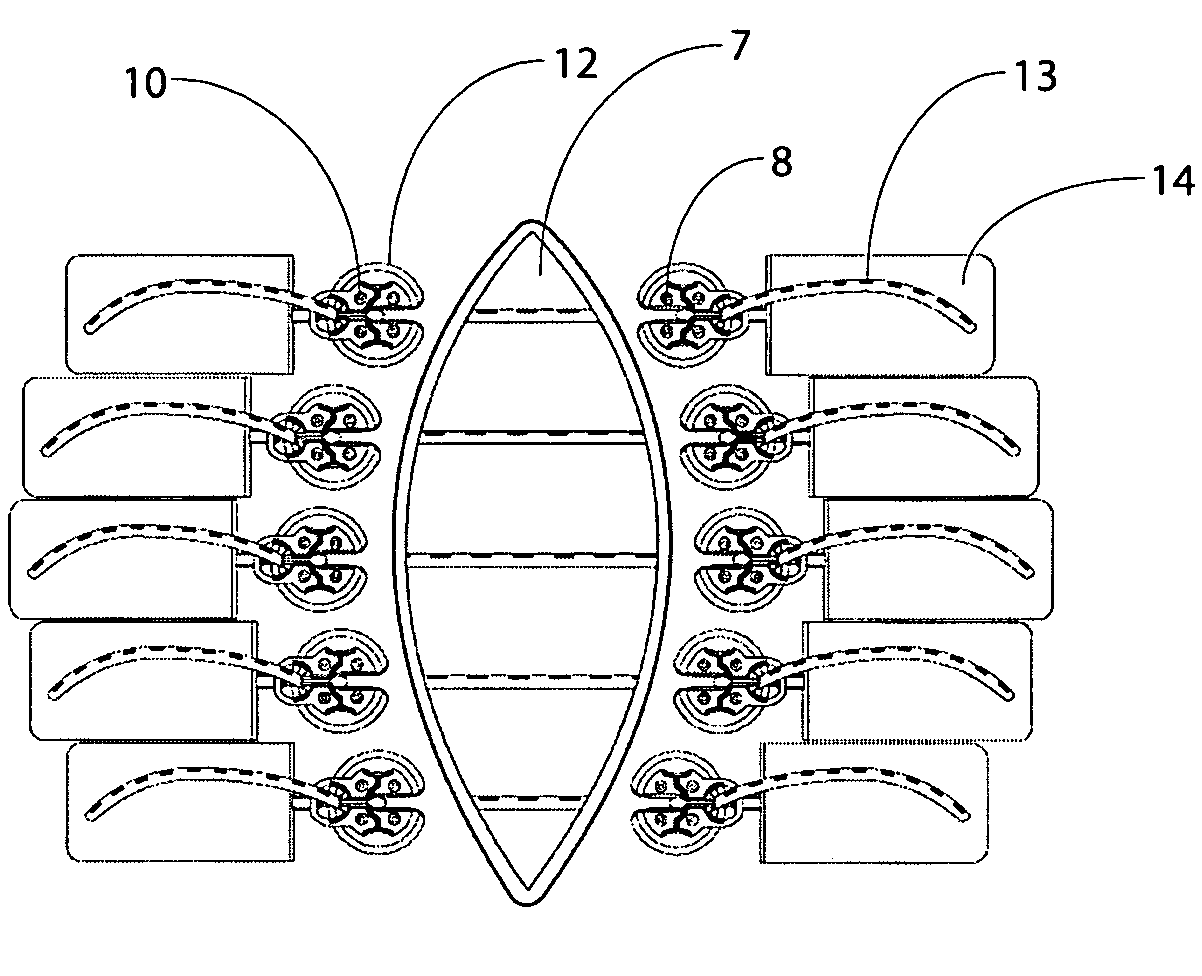
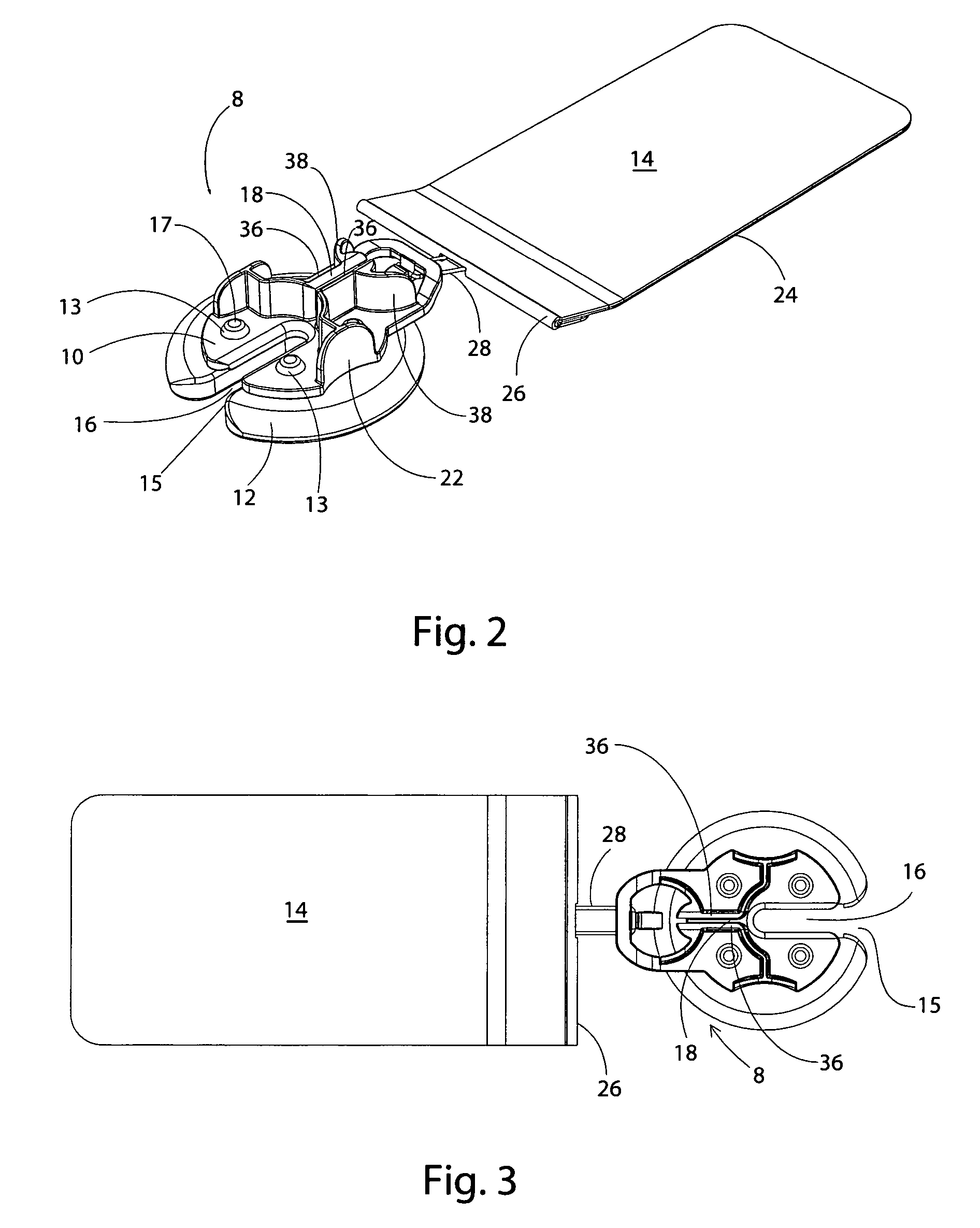
[0032] Anchors of this invention are used to transmit and distribute force to the tissue to be moved or stretched. A force applying component according to this invention may be formed in rods, cords, bands, loops, sheets, nets, wires, strands, cables, tubes or other suitable structure. In one embodiment, the fac is an elastic strand that flattens out at the point of maximum load and becomes load dissipating. In one embodiment, a rod-shaped fac is driven through the tissue using a cannula-like device and is attached at each end to an anchor.
[0033] Force applying components (“facs”) of this invention may have elastic properties “efacs”) and may be made from any suitable elastomeric material, including, without limitation, latex rubber, silicone, natural rubber and materials of similar elasticity, GR-S, neoprene, nitrile-butyl-polysulfide, ethylene-polyurethane, polyurethane, or any other suitable material that exhibits the property of exerting a return force when held in an elongated state at tensions and distances that are useful in the context of this invention. Efacs may provide a dynamic opposing force equal to or greater than the naturally occurring elastomeric traction forces of the tissue. The efacs of this invention generally are not endless loops but rather are lengths of a single strand, sometimes called a “monostrand,” and may be either solid or hollow. In some instances, multiple strands or endless loops or bands may be used. Significantly, the efacs used in practicing this invention may be secured to a tissue attachment structure at virtually any point along the efac, providing variable tension within the elastic limits of the elastomer used. Use of a non-reactive fac is generally desirable. Non-reactive facs include components that are either immunologically inert or hypoallergenic, such a elastomers formed from silicone or a hypoallergenic form of latex rubber.
[0034] Elastomers having various durometers may be used for the force applying components of this invention. Although other elastomeric materials and sizes of material may be used, polyurethane, thermoplastic (TPE) or rubber elastomer in monofilaments 1 mm-8 mm in diameter have been found to be useful in practicing this invention.
[0035] In one embodiment, an efac has a 0.125 inch diameter with a nominal durometer of 40. Other efacs, such as efacs having a smaller diameter, may also be provided and differentiated one from another based on color. Alternative shapes, sizes and strengths may be appropriate in some situations. An extruded silicone efac may have a durometer of 40 (which allows a 5:1 stretch ratio). A molded silicone efac may have a durometer of 5 (which allows a 12:1 stretch ratio). In one example, a secure mechanical lock may be achieved by restraining the efac within a constricting aperture of a size greater than the tensioned diameter but less than the untensioned diameter, such that the untensioned end of the elastomer acts as a restraint upon the aperture.
[0036] Force applying components can include marks indicating tension or stretch. The indicia may be formed from colorant, including any means for providing visual contrast, such as ink, dye, paint, or the like. Force applying components may also be disposable.
[0037] As noted above, it is generally desirable to use a non-reactive elastomeric force applying component such as a silicone, but silicone is normally difficult to secure. The viscoplastic properties of low durometer material, such as silicone, fall below the threshold where the material will hold a knot. Adequate constricting force may not be applied upon the material by the material itself to retain it under load because the application of the load reduces the material diameter beyond the minimum compression diameter of the constricting loop. This precludes the use of conventional surgical knot tying techniques because such knots will not hold. An additional complication is the tendency of the material to creep, or slip, when alternative capture methods are used. Thus, it is difficult to secure a silicone efac when a force is applied to the efac without the efac being cut or otherwise caused to fail by the securing structure.
[0038] Successful structures for securing a silicone elastomer (or other low durometer material) must clamp the silicone elastomer structure with enough force to hold it in place (avoiding creep) but with sufficiently distributed force that the elastomer is not severed. This invention provides structures that result in sufficient contact between an efac (including a silicone efac) and anchor structure that the two do not slide relative to each other while avoiding cutting or tearing the efac. Such structure can be provided by squeezing the efac between, or forcing it against, planar or relatively large radius arcuate surfaces while avoiding contact between the efac and arrises (intersections of planar surfaces) that might cut the elastomer.
[0039] Such a structure can be achieved with opposed planar or arcuate surfaces forming a Vee-shape and oriented so that tension on the efac forced into the gap between the surfaces will cause any reduction in outer diameter of the efac, such as occurs with added load, to result in the efac securing purchase lower in the Vee. In this manner, the efac-to-anchor structure contact is maintained, thereby improving the lock between the elastomer and anchor structure. Similarly, parallel surfaces may be engineered to provide an entrapment force and prescribed release tension for the efac in order to provide a maximum applicable tension and integral safety release.
[0040] The opposed surfaces can be provided by a variety of structures, such as arcuate surfaces provided by suitably rigid round wire or rod or by rounded opposed edges of plates of metal, plastic or other suitable material. Such structure can also be provided in other forms. For instance, the opposed surfaces between which the efac is trapped can also be provided by opposed flanges, typically positioned on a post or column and shaped so that the opposed flange surfaces get progressively closer together at points nearer the column. In such a structure, a first one of the opposed surfaces can be planar and can be, for instance, a flat base, provided that the other flange or other efac contact structure provides a surface that gets progressively closer to the first surface as the efac moves in the direction force applied to it during use will cause it to tend to move. For instance, the other flange can present a truncated conical surface.
[0041] As shown in FIGS. 1-3, a button anchor 8 of this invention comprises an anchoring portion 10, which rests on an anchor pad 12 and which can optionally engage a load distributing anchor tail 14. This button anchor 8 remains external to the human or animal tissues, and comprises specific features for anchoring a fac traveling across a wound or through tissues that, by its presence and ability to apply a reducing force, provides the specific benefit of moving or moving and stretching tissue to bring reduction or closure of a full thickness wound where the wound margins lie beyond a distance where they can be primarily closed without undue force. In one example, a fac is passed through the skin, engaging or encircling the sub-dermal structures requiring closure, and returned through the skin on the other side of a wound or incision. The button anchors 8 are applied to the ends of the fac, allowing the fac to be tensioned and anchored, thereby applying a sub-dermal reduction force, as illustrated in FIG. 1. In an alternative embodiment, button anchors 8 positioned on opposite sides of a wound secure a fac that passes over the wound and that does not penetrate the tissue.
[0042] As shown in FIGS. 2-5, the anchoring portion 10 has a large slot 16 and a smaller slot 18 for engagement of an efac, such as an elastomer. Slot 18 includes walls 36 and is a metered tension, elastomer-locking slot, with a shape, length and size such that the slot 18 captures and anchors the elastomer but allows the elastomer to migrate if tension exceeds a pre-determined level, thereby creating a limit to the amount of force that can be applied by the system. This limit is determined at the time of manufacture of the anchoring portion 10 by controlling the relationship between the size of the slot 18 and the diameter or cross-sectional area of the elastomer. The cross-sectional area of the untensioned portion of the elastomer decreases as the elastomer elongates under increased tension. If a force applied to the elastomer exceeds the therapeutic force range, elongation and resulting reduction in diameter cause the elastomer to release within the slot, returning the quantity of tension to one within the therapeutic limit of the elastomer.
[0043] Convex upstanding regions 38 (visible in FIGS. 1 and 4) of the anchoring portion 10 prevent other objects from catching the edges of the button anchor 8.
[0044] The anchoring portion 10 may be molded of polycarbonate plastic or any other appropriately rigid and strong polymeric material suitable for use in the surgical applications for which the present invention is intended. Alternatively it may be molded, machined or otherwise formed or fabricated of any other suitably strong, surgically acceptable material such as stainless steel.
[0045] While the size of the button anchor 8 of this invention may be varied depending on the situation in which it is used, anchoring portion 10 may be approximately 32 mm in diameter. An anchoring portion 10 for use with an elastomeric three mm diameter, 40 durometer silicone cord may have a slot 18 one mm in width (i.e., the distance between walls 36), 7.3 mm in height and 11 mm in length. Many other dimensions are also usable provided that the desired coupling with elastomer is achieved (generally as described above).
[0046] Various arcuate or curved surface shapes for anchor efacs attachment structures are described above. It should be understood that functionally equivalent shapes can also be used, such as, for instance, a rod having a cross-section that is not curved but rather is a polygon.
[0047] As shown in FIGS. 6 and 7, anchor pad 12 includes a slot 15 that corresponds to slot 16 of the anchoring portion 10. Anchor pad 12 dissipates the compression load exerted by one or more facs connected to the anchoring portion 10 over the surface of the patient's skin and works to prevent maceration or undue restriction of the underlying blood circulation. The anchor pad 12 is generally the same size and shape as the anchoring portion 10, but it may be smaller or larger in alternative embodiments. For example, larger pads may be used in patients with compromised skin tissues, including the elderly or those with associated co-morbidities, such as diabetes.
[0048] The anchor pad 12 may be made of a compressible material such as silicone, or any other suitable material. The skin contact surface (i.e., the underside) of anchor pad 12 may be smooth or it may be textured in order to accommodate fluid dissipation. The skin contact surface may be flat, convex, concave or multi-planar to accommodate anatomical contour. The skin-contacting surface of pad 12 may also be coated or treated to provide antimicrobial properties. In one embodiment, the skin-contacting surface of the anchor pad includes an adhesive.
[0049] As shown in FIG. 5, the anchoring portion 10 is penetrated by apertures 20 that secure the anchoring portion 10 to the anchor pad 12. Tabs 13 (shown in FIG. 7) project from anchor pad 12 and are received in apertures 20 of anchoring portion 10. Enlarged diameter end 17 of tabs 13 retain anchoring portion 10 on pad 12. In an alternative embodiment, the anchor pad 12 is adhered, adhesively bonded, or molded to anchoring portion 10. In one example, the anchor pad 12 and anchoring portion 10 are an integral unit.
[0050] As shown in FIGS. 2 and 5, finger grips 22 facilitate gripping and manipulating the button anchor 8 by opposed digits. Finger grips 22 are concave in the embodiment illustrated in the drawings, but the gripping portion may also be convex, multi-planar or textured.
[0051] Optional anchor tail 14, shown in FIGS. 2, 3 and 8, may be utilized to further dissipate and distribute the shear-load placed on the skin by performing wound closure over the maximum possible surface area. In one embodiment, the anchor tail 14 is formed from polyurethane foam having an adhesive for attachment to the skin and includes a wire that forms a loop 28 at end 26. In alternative embodiments, the anchor tail 14 may be formed from any suitable fabric, foam or film. Such material may be elastic or inelastic. Preferably the anchor tail 14 material conforms to the skin surface and mimics the elasticity of the skin. In addition, the loop 28 may be formed or molded as a separate or integral component.
[0052] Anchoring portion 10 of button anchor 8 includes structure for engaging anchor tail 14. Such structure may include a hole, tab, cleat or other suitable structure. In one embodiment, shown in the Figures, and particularly in FIG. 9, the anchoring portion 10 includes a hook 30 having a ramp 32 for guiding the wire loop 28 of tail 14 up and into depression 34 of anchoring portion 10. In use, the anchor tail 14 is attached to the anchoring portion 10 via the engagement hook 30 and is adhered to the skin. In this manner, anchor tail 14 bolsters the button anchor 8 and dissipates the forward force load (a force vector that travels toward the wound edge and parallel to the skin surface) over a large area of healthy skin located behind the button anchor 8. While the hook 30 and loop 28 provide one example of structure to couple the anchor tail and anchor, any suitable structure may be used.
[0053] The system of this invention may be used to provide deep fascia repair and deep fascia dynamic wound reduction. In one embodiment, illustrated in FIG. 10, a silicone elastomer 13 is coupled to a cannula-like device 42 and is passed through the dermis 44, fat layer 46, and fascia 48 at an optional anchor placement mark 50 placed on the skin prior to installation of the system. After passing through the area of the wound 7, the elastomer 13 is presented through slot 16 of anchoring portion 10 and slot 15 of anchor pad 12 of button anchor 8, where it is then captured and secured in smaller slot 18 of anchoring portion 10. In this manner, closure force is applied to a wound or incision 7. Multiple sets of anchors and elastomers may be used, as shown in FIG. 1.
[0054] The elastomer 13 may either be presented through the skin and through the slot 16 of an anchor previously placed, or the elastomer 13 may exit the skin, at which time the slot 16 and the pad slot 15 of the anchor 8 may be moved into place around the elastomer 13. The efac may be used to apply tension to sub-dermal structures (deep fascia) but the efac tension may be adjusted from above the skin by increasing or decreasing the tension at the smaller slot 18. The anchor 8 acts as a grommet, removes the point load from the exit hole to reduce the occurrence of localized failures, and also allows adjustment of the tension across the wound. In this manner, the anchor bolsters the perimeter of the transcutaneous opening through which the elastomer passes, reducing localized failures and also reducing scarring.
[0055] A system according to this invention may provide wound stabilization of abdominal procedures. For example, this system may be used to restore radial abdominal integrity during prolonged interventions for complications such as abdominal infections management or which require large abdominal access. This system increases patient comfort and mobility by providing abdominal containment and support, and maintains normal skin tensions during intervention to minimize retraction.
[0056] Another system of this invention may provide stability to sternal or chest non unions as can arise after open heart surgical procedures. In addition, systems of this invention may be used with conventional primary wound closure methods to distribute skin system tensions to healthy skin beyond the wound, thereby minimizing stress at the wound site and reducing dehiscence. A system of this invention may be applied pre-operatively to tension skin and create surplus tissue, allowing excisions to be covered and closed in a conventional manner. Embodiments of this invention may also be used as a dressing retention system by providing efac lacing across the wound site, which passes over the wound dressing and secures it in position. Adhesives may be used on the skin contacting surface of the anchor pad but such adhesives normally would not be required, thereby further facilitating the periodic inspection and cleaning of tissues under the anchor pads.
[0057] All of the tissue attachment structure and anchor designs described herein may be produced in a variety of sizes.
[0058] The systems and methods of moving or moving and stretching plastic tissue according to this invention are not confined to the embodiments described herein but include variations and modifications within the scope and spirit of the foregoing description and the accompanying drawings. For instance, the scale of the components of the invention can vary quite substantially depending on the nature and location of the tissue with which the invention is used. The configuration of the tissue attachment structures can also be varied for the same reasons and for aesthetic reasons. While most of the elements of the illustrative embodiments of the anchors of this invention depicted in the drawings are functional, aspects of the shape and appearance of the illustrative embodiments are nonfunctional and ornamental.
[0059] The materials from which the components used in practicing this invention are made can be those described above as well as others, including materials not yet developed that have appropriate properties of strength, elasticity and the like that will be apparent to those skilled in the art in light of the foregoing. For instance, useful materials generally must be sterile or sterilizable and non-reactive. The illustrated components are typically intended to be disposable, but the invention can also be practiced using reusable components.

PUM

no PUM

Description & Claims & Application Information

We can also present the details of the Description, Claims and Application information to help users get a comprehensive understanding of the technical details of the patent, such as background art, summary of invention, brief description of drawings, description of embodiments, and other original content. On the other hand, users can also determine the specific scope of protection of the technology through the list of claims; as well as understand the changes in the life cycle of the technology with the presentation of the patent timeline. Login to view more.

Similar technology patents

Wall thickness measurement tool of simple and cylindrical cabin casting

PendingCN110160428ASimple and easy to useEasy to readMechanical thickness measurementsEngineeringLeft–right symmetry
Owner:BEIJING HANGTIAN XINFENG MECHANICAL EQUIP

Release pin

ActiveUS20180283433A1Simple and easy to useEasy to useSeating arrangementsDowelsMechanical engineering
Owner:BE AEROSPACE INCORPORATED

Research Report Search System

InactiveUS20070255692A1Facilitate searchingSimple and easy to useWeb data indexingSpecial data processing applicationsInformation retrievalResearch reporting
Owner:YOUSUF AHMED KHALIFA

Female urination device

InactiveUS20130066287A1Simple and easy to useConvenient to carryRestraining devicesNon-surgical orthopedic devicesFemale urination deviceUrine
Owner:MA

Modular wall mount enclosure

ActiveUS20200015377A1Simple and easy to useSide-by-side/stacked arrangementsClosed casingsAnimal scienceEngineering
Owner:HUBBELL INC

Classification and recommendation of technical efficacy words

  • Cost-effective
  • Simple and easy to use

Barrel accessory rail system

InactiveUS20050217161A1Simple and easy to useAffect performanceSighting devicesBarrelsFastenerEngineering
Owner:RA BRANDS

Personal computer protection device

InactiveUS6961856B1Simple and easy to useEconomical in cost to manufactureDigital data processing detailsVolume/mass flow measurementPower sensorPersonal computer
Owner:PC FAILSAFE

Electro-stimulation device to pump blood from legs

InactiveUS8175713B1Simple and easy to useEconomical in cost to manufactureBlood stagnation preventionElectrotherapyBlood circulationElectricity
Owner:VEINOPLUS HONG KONG
Why Eureka
Try Eureka