Printing apparatus, printing method, and medium

a printing method and printing method technology, applied in the direction of printing and inking apparatus, etc., can solve the problems of complex configuration, increased cost, and complex system, and achieve the effect of simple configuration, and reduced the concentration of liquid flowing

Active Publication Date: 2017-07-13
CANON KK
View PDF2 Cites 8 Cited by
  • Summary
  • Abstract
  • Description
  • Claims
  • Application Information

AI Technical Summary

Benefits of technology

[0007]The present invention is made in view of the above-described circumstances and an object of the present invention is to suppress an increase in concentration of a liquid flowing through a circulation system caused by an evaporation of a volatile component from an ejection opening without causing an increase in cost in terms of a simple configuration compared with the related art.

Problems solved by technology

However, in the technique disclosed in Japanese Patent Laid-Open No. 2005-271337, since the thick ink or the dilute solution is needed and a concentration sensor for at least one color is needed, the system becomes complex.
As a result, problems arise in that a configuration becomes complex and a cost increases.

Method used


Image

  • Printing apparatus, printing method, and medium
  • Printing apparatus, printing method, and medium
  • Printing apparatus, printing method, and medium

Examples


first application example

(Description of Inkjet Printing Apparatus)

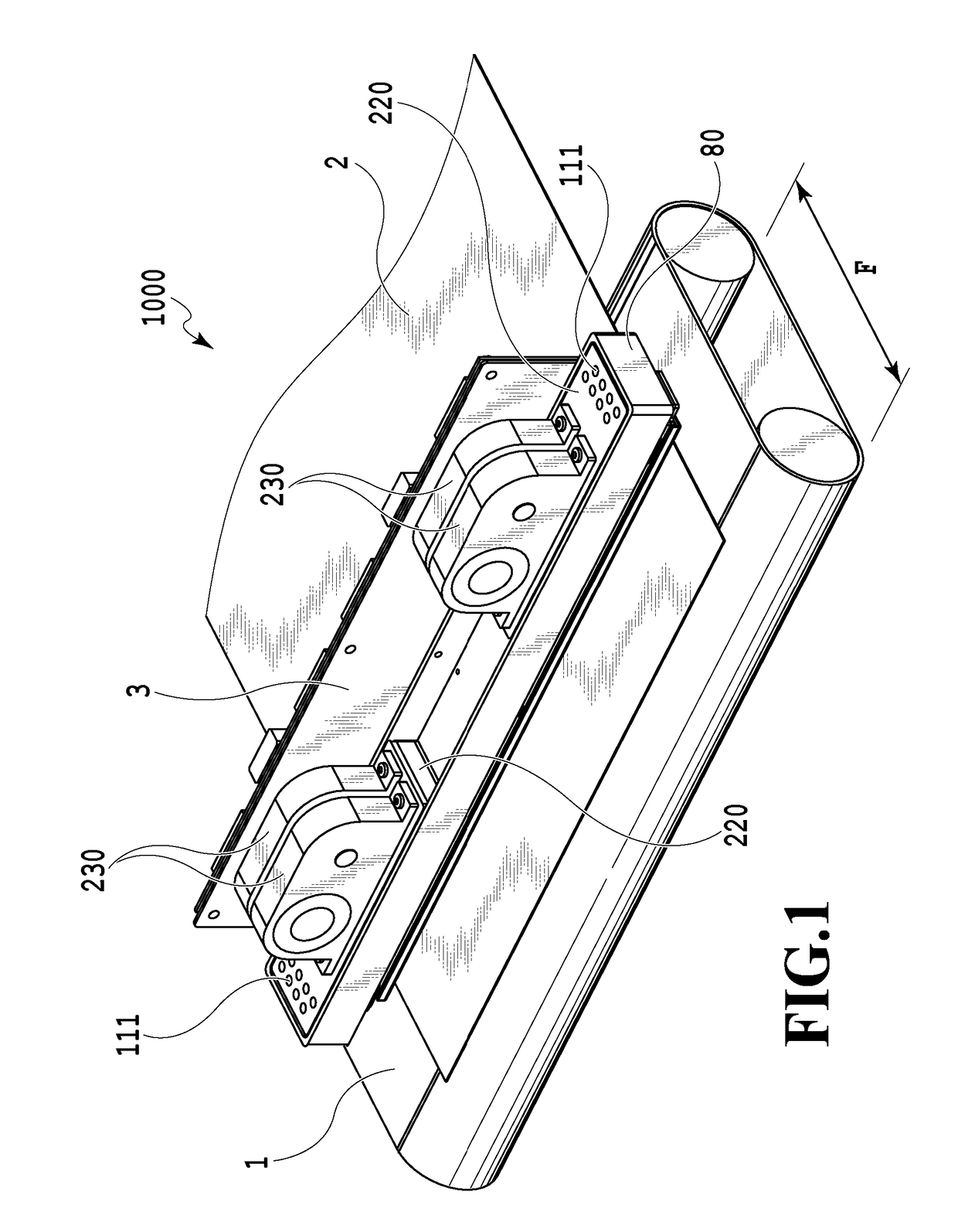
[0052]FIG. 1 is a diagram illustrating a schematic configuration of a liquid ejection apparatus that ejects a liquid in the present invention and particularly an inkjet printing apparatus (hereinafter, also referred to as a printing apparatus) 1000 that prints an image by ejecting ink. The printing apparatus 1000 includes a conveying unit 1 which conveys a print medium 2 and a line type (page wide type) liquid ejection head 3 which is disposed to be substantially orthogonal to the conveying direction of the print medium 2. Then, the printing apparatus 1000 is a line type printing apparatus which continuously prints an image at one pass by ejecting ink onto the relative moving print mediums 2 while continuously or intermittently conveying the print mediums 2. The liquid ejection head 3 includes a negative pressure control unit 230 which controls a pressure (a negative pressure) inside a circulation path, a liquid supply unit 220 which communi...

second application example

[0091]Hereinafter, configurations of an inkjet printing apparatus 2000 and a liquid ejection head 2003 according to a second application example of the invention will be described with reference to the drawings. In the description below, only a difference from the first application example will be described and a description of the same components as those of the first application example will be omitted.

(Description of Inkjet Printing Apparatus)

[0092]FIG. 21 is a diagram illustrating the inkjet printing apparatus 2000 according to the application example used to eject the liquid. The printing apparatus 2000 of the application example is different from the first application example in that a full color image is printed on the print medium by a configuration in which four monochromic liquid ejection heads 2003 respectively corresponding to the inks of cyan C, magenta M, yellow Y, and black K are disposed in parallel. In the first application example, the number of the ejection openin...

third application example (embodiment)

(Description of Configuration of Liquid Ejection Head)

[0106]Hereinafter, a configuration of a liquid ejection head 400 according to the embodiment will be described. Further, in the description below, only a difference from the above-described embodiments will be mainly described and a description of the same components as those of the above-described embodiments will be omitted. FIG. 22 is a perspective view illustrating the liquid ejection head 400 according to the embodiment. Here, a coordinate axis is set as illustrated in the drawings for the description of the embodiment.

[0107]Referring to FIG. 22, one elongated liquid ejection head 400 has a configuration in which a plurality of print element boards 420 having a plurality of print elements ejecting a liquid such as ink and densely arranged are arranged on a passage member 410 in the X direction while being alternately deviated from each other in the Y direction. An overlapping area (indicated by “L” in FIG. 22) is provided be...


PUM


Abstract

In a printing apparatus including a circulation system circulating a liquid, a volatile component included in the liquid evaporates from an ejection opening and thus characteristics of the liquid involving with concentration or viscosity change. The invention provides a printing apparatus that uses a liquid ejection head including an ejection opening ejecting a liquid, a print element generating energy for ejecting a liquid, and a pressure chamber having the print element provided therein, the printing apparatus including: a circulator configured to circulate the liquid so that the liquid passes through the pressure chamber; and a concentration adjustment unit configured to adjust a concentration of a liquid inside a liquid circulation system by discharging the liquid from the inside of the liquid circulation system and replenishing the liquid into the liquid circulation system from the outside of the liquid circulation system in response to the amount of the discharged liquid.

Description

BACKGROUND OF THE INVENTION[0001]Field of the Invention[0002]The present invention relates to a printing apparatus, a printing method, and a medium.[0003]Description of the Related Art[0004]In the field of an inkjet printing head, since a volatile component of ink evaporates from an ejection opening, characteristics of the ink in the vicinity of the ejection opening change. Accordingly, some problems arise in that unevenness in color is caused by a change in color concentration and deterioration in landing accuracy is caused by a change in ejection speed in accordance with an increase in viscosity. As a countermeasure for such problems, there is known a method of circulating ink supplied to an inkjet printing head through a circulation path. However, in this method, since the ink is circulated so that fresh ink is supplied to a front end of a nozzle at all times, moisture normally evaporates from the front end of the nozzle. As a result, a problem arises in that a concentration of i...

Claims


Application Information

Patent Timeline
Patent Type & Authority Applications(United States)
IPC IPC(8): B41J2/045
CPCB41J2/04586B41J2/04535B41J2/14B41J2/18B41J2/1404B41J2/155B41J2/16505B41J2/16526B41J2/16585B41J2002/14362B41J2202/12B41J2202/20
Inventor KARITA, SEIICHIROIWANAGA, SHUZOYAMADA, KAZUHIROAOKI, TAKATSUNAOKUSHIMA, SHINGOTAMENAGA, ZENTAROKOMAMIYA, YUMINAGAI, NORIYASUMORI, TATSUROUNAKAGAWA, YOSHIYUKIYAMAMOTO, AKIRA
Owner CANON KK
Why Eureka
Try Eureka