Wavelength conversion element, illumination device, and projector
a technology of wavelength conversion and illumination device, which is applied in the direction of instruments, projectors, optics, etc., can solve the problem that the color balance deviation due to aging in use cannot be adjusted, and achieve the effect of small change in color balan
- Summary
- Abstract
- Description
- Claims
- Application Information
AI Technical Summary
Benefits of technology
Problems solved by technology
Method used
Image

Examples
first embodiment
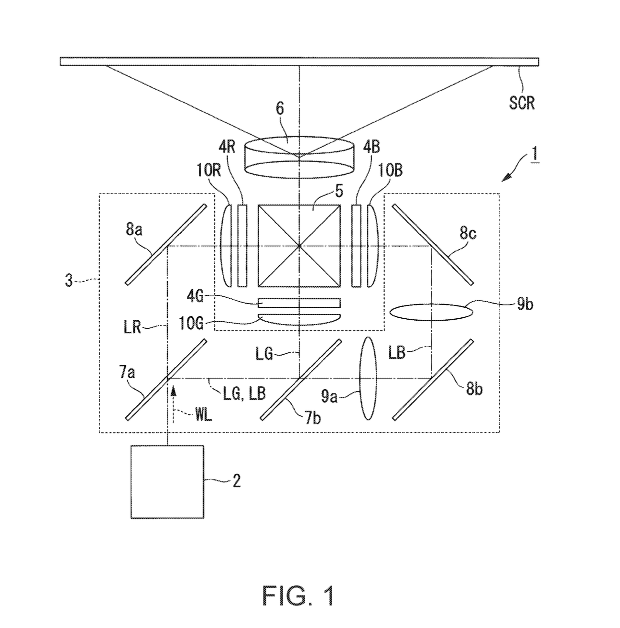
[0040]FIG. 1 is a schematic configuration diagram of a projector of a first embodiment.
[0041]As shown in FIG. 1, the projector 1 of the embodiment is a projection-type image display device that displays a color image on a screen SCR. The projector 1 uses three light modulators corresponding to respective colored lights; red light LR, green light LG, and blue light LB. The projector 1 uses, as a light source of an illumination device 2, a semiconductor laser from which high-luminance, high-output light is obtained.
[0042]The projector 1 roughly includes the illumination device 2, a color separation optical system 3, a light modulator 4R for red light, a light modulator 4G for green light, a light modulator 4B for blue light, a combining optical system 5, and a projection optical system 6.
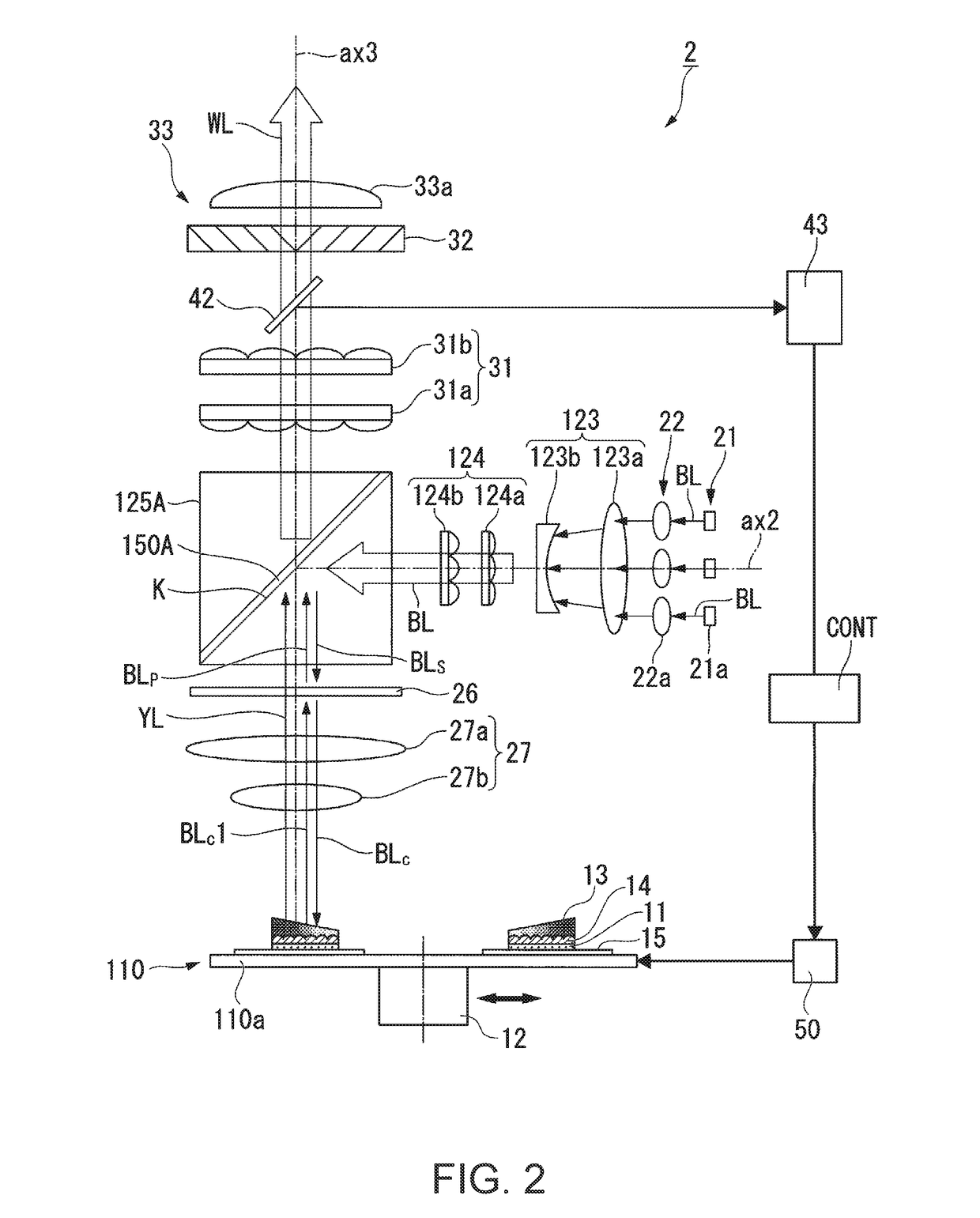
[0043]The illumination device 2 emits white illumination light WL toward the color separation optical system. 3. A wavelength conversion element as one embodiment of the invention, to be described lat...
second embodiment
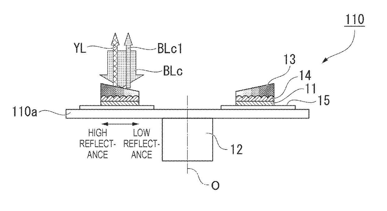
[0120]In the above embodiment, the dichroic film 13 in which the reflectance distribution continuously changes from the inner circumferential side toward the outer circumferential side of the rotating substrate 110a has been exemplified. However, the invention is not limited to this, and a change in reflectance distribution may be discontinuous in the dichroic film.
[0121]FIG. 8 is a diagram showing a configuration of a phosphor wheel 210 according to a second embodiment. FIG. 9 is a cross-sectional view taken along line C-C in FIG. 8. In FIGS. 8 and 9, members common to the above embodiment are denoted by the same reference numerals and signs.
[0122]As shown in FIG. 8, a dichroic film 113 in the phosphor wheel 210 includes a plurality of regions B having a ring shape centered on the axis O of rotation of the rotating substrate 110a.
[0123]The reflectance is constant in each of the regions B, but the reflectance is different in each of the regions B. The reflectance of the region B lo...
third embodiment
[0126]In the above embodiment, the case of using the phosphor wheel 110 has been exemplified. However, the illumination device 2 is not limited to this configuration. For example, the phosphor layer may be provided on a non-rotatable base material.
[0127]FIG. 11 is a diagram showing a configuration of a dichroic film 213 according to a third embodiment. Although illustration is omitted in FIG. 11, the dichroic film 213 is formed on the phosphor layer provided on a non-rotatable base material. In FIG. 11, the spot diameter of the excitation light at the incident position IP is shown enlarged for clarity of illustration.
[0128]As shown in FIG. 11, the dichroic film 213 includes, in this order regions D1, D2, D3, D4, and D5 having different reflectances along a direction in which the incident position IP of the excitation light on the dichroic film 213 moves, that is, along the translational direction of the dichroic film 213 (base material). For example, the reflectance of the region D1...
PUM
 Abstract
Description
Claims
Application Information
 - R&D
- Intellectual Property
- Life Sciences
- Materials
- Tech Scout
- Unparalleled Data Quality
- Higher Quality Content
- 60% Fewer Hallucinations
Browse by: Latest US Patents, China's latest patents, Technical Efficacy Thesaurus, Application Domain, Technology Topic, Popular Technical Reports.
© 2025 PatSnap. All rights reserved.Legal|Privacy policy|Modern Slavery Act Transparency Statement|Sitemap|About US| Contact US: help@patsnap.com