
Senising on uavs for mapping and obstacle avoidance

a technology of obstacle avoidance and sensing, applied in the field of uavs, can solve the problems of limited ladar choices that can fit the swap requirements, vehicle blindness in the direction of travel at high speeds, and few well-suited sensors

Inactive Publication Date: 2017-07-13
ROBOTIC RES OPCO LLC
View PDF5 Cites 34 Cited by
  • Summary
  • Abstract
  • Description
  • Claims
  • Application Information

AI Technical Summary

Benefits of technology

The laser projection system creates vertical lines that are viewed by cameras at different positions. This creates a stereo disparity, which allows the lines to be triangulated in 3D space. The cameras can rotate to provide full 360 degree range sensing capabilities. The technical effect of this system is the ability to accurately sense and measure the 3D space around a laser line.

Problems solved by technology

There are few sensors that are well suited for autonomous mobility and mapping functions on small aerial platforms.
LADAR choices that can fit the SWAP requirements are severely limited; few LADARs are available within the SWAP.
Therefore, if a sensor with relatively small vertical field of view is installed horizontally, the vehicle will be blind in the direction of travel at high speeds.
However, in both cases, poor lighting of an indoor environment—together with the lower quality optics camera combinations that can be carried with the quads—makes it a poor choice.
Many attempts like this have been performed in the past few years, with very poor results.
UGVs can be used for many applications where it may be inconvenient, dangerous, or impossible to have a human operator present.

Method used


Image

  • Senising on uavs for mapping and obstacle avoidance
  • Senising on uavs for mapping and obstacle avoidance
  • Senising on uavs for mapping and obstacle avoidance

Examples


Embodiment Construction

[0030]In the following detailed description of the invention of exemplary embodiments of the invention, reference is made to the accompanying drawings (where like numbers represent like elements), which form a part hereof, and in which is shown by way of illustration specific exemplary embodiments in which the invention may be practiced. These embodiments are described in sufficient detail to enable those skilled in the art to practice the invention, but other embodiments may be utilized and logical, mechanical, electrical, and other changes may be made without departing from the scope of the present invention. The following detailed description is, therefore, not to be taken in a limiting sense, and the scope of the present invention is defined only by the appended claims.

[0031]In the following description, numerous specific details are set forth to provide a thorough understanding of the invention. However, it is understood that the invention may be practiced without these specifi...


PUM


Abstract

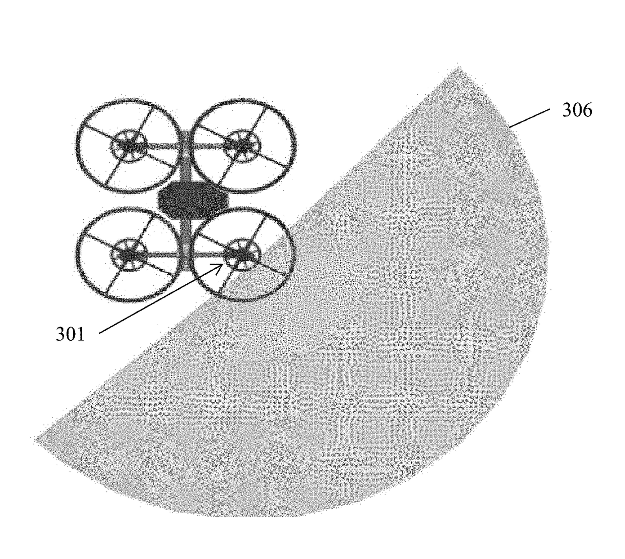
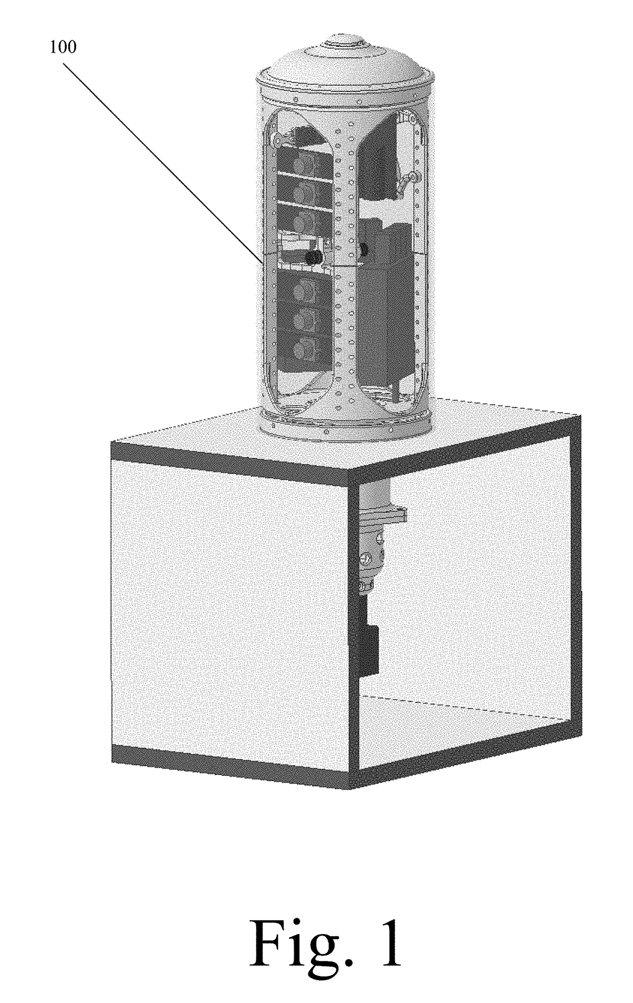
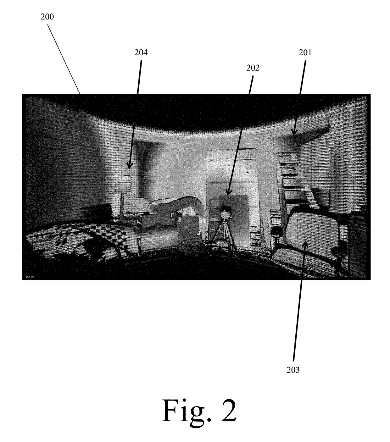
Structured light approaches utilize a laser to project features, which are then captured with a camera. By knowing the disparity between the laser emitter and the camera, the system can triangulate to find the range. Four, 185 degree field-of-view cameras provide overlapping views over nearly the whole unit sphere. The cameras are separated from each other to provide parallax. A near-infrared laser projection unit sends light out into the environment, which is reflected and viewed by the cameras. The laser projection system will create vertical lines, while the cameras will be displaced from each other horizontally. This relative shift of the lines, as viewed by different cameras, enables the lines to be triangulated in 3D space. At each point in time, a vertical stripe of the world will be triangulated. Over time, the laser line will be rotated over all yaw angles to provide full a 360 degree range.

Description

CROSS REFERENCE TO RELATED APPLICATIONS[0001]This application claims priority from U.S. Patent Application Ser. 62 / 175,231, entitled “SENISING ON UAVS FOR MAPPING AND OBSTACLE AVOIDANCE”, filed on 13 Jun. 2015. The benefit under 35 USC §119(e) of the United States provisional application is hereby claimed, and the aforementioned application is hereby incorporated herein by reference.FEDERALLY SPONSORED RESEARCH[0002]Not ApplicableSEQUENCE LISTING OR PROGRAM[0003]Not ApplicableTECHNICAL FIELD OF THE INVENTION[0004]The present invention relates to UAVs. More specifically, the present invention is related to providing structured light and time of flight sensors on UAVs for obstacle avoidance and creating mapping capabilities.BACKGROUND OF THE INVENTION[0005]There are few sensors that are well suited for autonomous mobility and mapping functions on small aerial platforms. LADAR choices that can fit the SWAP requirements are severely limited; few LADARs are available within the SWAP. One...

Claims


Application Information

Patent Timeline
IPC IPC(8): H04N13/02G01S17/93G01S7/481B64D47/08H04N5/232B64C39/02B64C27/08G01S17/89G01S17/02G01S17/933
CPCH04N13/0242B64C2201/162G01S17/933G01S7/4813G01S17/023H04N5/23238H04N13/0271B64C39/024B64C27/08B64D47/08H04N2013/0081H04N13/0022B64C2201/024B64C2201/108G01S17/89G01S17/08G01S17/42G01S17/48G01S7/4815G01S7/4816H04N13/254G01B11/245G01B11/2518G01B11/2545H04N13/243B64U2201/00B64U2101/30B64U10/14H04N13/128H04N13/271B64U50/14
Inventor LACAZE, ALBERTO DANIELMURPHY, KARL NICHOLASWILHELM, III, RAYMOND PAUL
Owner ROBOTIC RES OPCO LLC
Learn More