Eureka AIR delivers breakthrough ideas for toughest innovation challenges, trusted by R&D personnel around the world.

LED illumination apparatus

Active Publication Date: 2017-07-20
NAT TAIWAN UNIV
View PDF2 Cites 0 Cited by
  • Summary
  • Abstract
  • Description
  • Claims
  • Application Information

AI Technical Summary

Benefits of technology

The LED illumination apparatus described in this patent text reduces heat generation using LEDs as light sources. The up-and-down arrangement of LEDs allows for a higher number of LEDs to achieve the required illumination intensity. The heat pipe helps to effectively direct heat from the base of the apparatus to the heat-dissipating fins, which disperse the heat to the ambient air for better heat dissipation. The overall volume of the apparatus can be reduced while disposing as much dissipating fins as possible. Additionally, the apparatus has a water-proofing rubber ring to prevent water or water vapor from entering the lamp cup and potentially damaging the circuit boards and LEDs.

Problems solved by technology

However, since tungsten light bulbs have a shorter service life and consume more power to reach certain illumination intensity, one of the major consequences is excessive temperatures.
Since tungsten light bulbs generate more heat, when the light bulbs are exposed continuously under excessive temperature condition, the service life of light bulbs is shortened.
Other issues include increased replacement rate and maintenance fee.
But in order to meet the requirements of head lights for rail cars, since the head lights consume more power, the manufacturing price of the product is also higher.
This scenario leads to higher sales price on the market.
However, during the manufacturing stage, because such practice requires concentrating each LED with the lens, the manufacturing process is more complicated relative to tungsten light bulbs.
The manufacturing cost also increases since multiple lenses must be used.

Method used


Image

  • LED illumination apparatus
  • LED illumination apparatus
  • LED illumination apparatus

Examples


Embodiment Construction

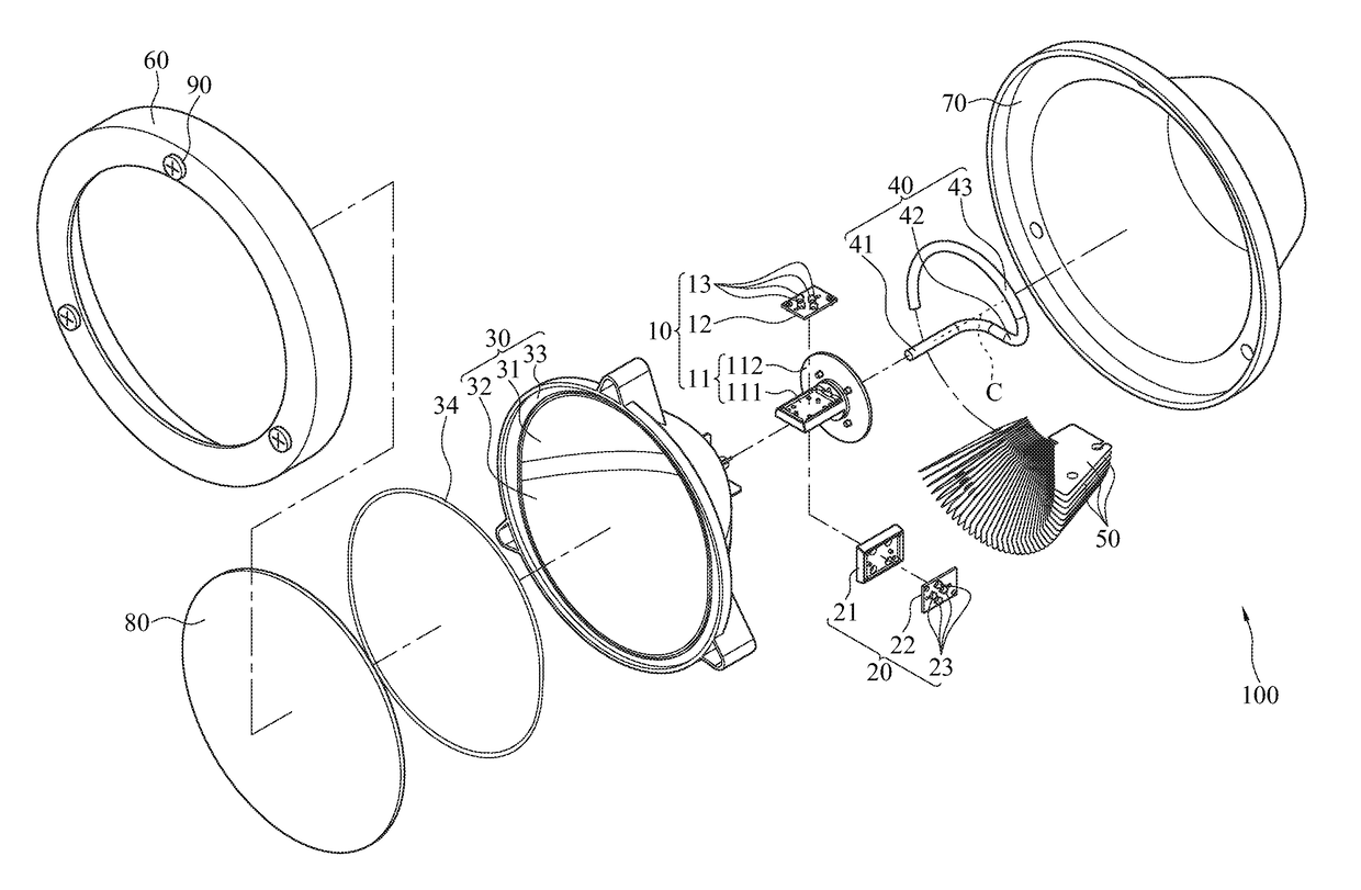
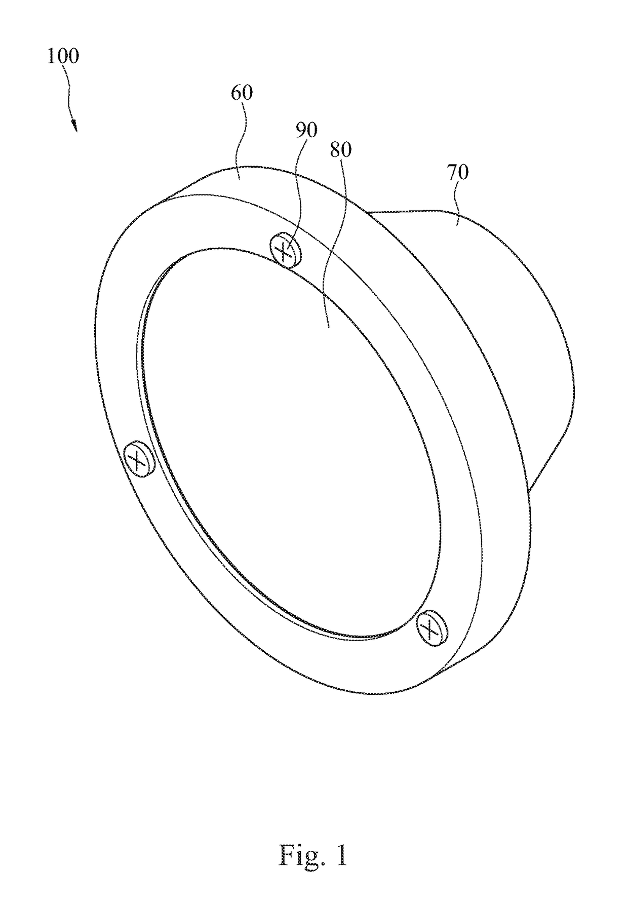
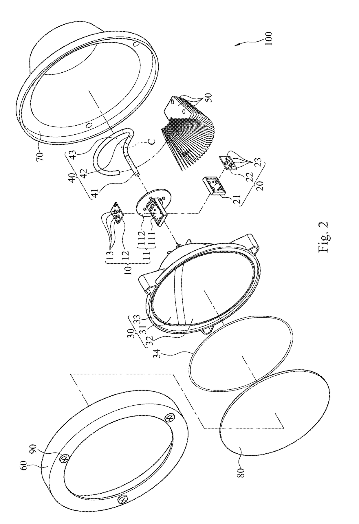
[0022]Please refer to FIGS. 1 to 3, where FIG. 1 is a schematic view of an LED illumination apparatus for one embodiment of the instant disclosure, FIG. 2 is an exploded view of the LED illumination apparatus for this embodiment of the instant disclosure, and FIG. 3 is a sectional view of the LED illumination apparatus for the same embodiment of the instant disclosure with some elements omitted. For the instant embodiment, an LED illumination apparatus 100 comprises a first lighting module 10, a second lighting module 20, a lamp cup 30, a heat pipe 40, a plurality of heat dissipating fins 50, a front cover 60, a rear cover 70, and a glass cover 80.

[0023]The first lighting module 10 includes a first base 11, a first circuit board 12, and a plurality of first light emitting diodes (LEDs) 13. For the instant embodiment, four first LEDs 13 are used for explanatory purposes. In other embodiments, one or more first LED 13 may be disposed depending on the required illumination. The four fi...


PUM


Abstract

An LED illumination apparatus includes a first lighting module, a second lighting module, a lamp cup, a heat pipe, and a plurality of heat dissipation fins. The first and second lighting modules are connected with each other and emit light in opposite directions, in addition being received by the lamp cup. The lamp cup includes two reflecting surfaces arranged in symmetrical mirror fashion. The light emitting from the first and second lighting modules are directed to respective reflecting surfaces and reflected toward a same direction by the reflecting surfaces. The heat pipe is disposed in between the first and second lighting modules. The heat dissipation fins are fitted over the heat pipe. The heat generated by lighting modules would transmit to the heat pipe and be guided to the heat dissipation fins in order to accelerate cooling.

Description

CROSS-REFERENCES TO RELATED APPLICATIONS[0001]This non-provisional application claims priority under 35 U.S.C. §119(a) on patent application No. 105101780 filed in Taiwan, R.O.C. on Jan. 20, 2016, the entire contents of which are hereby incorporated by reference.BACKGROUND[0002]Technical Field[0003]The instant disclosure relates to an LED illumination apparatus, in particular to an LED illumination apparatus having heat dissipating structures.[0004]Related Art[0005]Head lights of rail cars are different from typical illumination requirements. By considering the weight and speed of rail cars, its illumination is required to clearly illuminate objects far ahead on the rail, unlike typical indoor illumination for close distance and large area. Therefore, the light field associated with head lights of rail cars must meets specific regulations. Since for rail cars, its head lights must achieve a certain level of illumination for a specific distance and equivalent luminance, most rail car...

Claims


Application Information

Patent Timeline
IPC IPC(8): F21K99/00B61D29/00F21V31/00F21S8/10F21V29/71F21V7/04
CPCF21K9/137F21V29/717F21V7/045F21Y2101/02F21S48/1388F21S48/1159B61D29/00F21V31/005F21S45/50F21S41/321F21S45/10
Inventor SU, GUO-DUNGHSU, CHIH-HAO
Owner NAT TAIWAN UNIV
Why Eureka
Eureka Blog
Learn More