Optical lens

a technology of optical lenses and optical axis, applied in the field of optical axis, can solve the problems of chromatic aberration, inability to faithfully reflect processing in real-time, ccd monitoring system, etc., and achieve the effect of ensuring the quality of laser processing and better imaging

Active Publication Date: 2017-07-20
HANS LASER TECH IND GRP CO LTD
View PDF2 Cites 4 Cited by
  • Summary
  • Abstract
  • Description
  • Claims
  • Application Information

AI Technical Summary

Benefits of technology

[0015]The above-mentioned optical lens can be applied to an optical system of a laser processing apparatus, which uses wavelength in the far-infrared region as the wavelength for laser

Problems solved by technology

However, when the system uses far-infrared wavelength laser to process, there is chromatic aberration i

Method used


Image

  • Optical lens
  • Optical lens
  • Optical lens

Examples


Embodiment Construction

[0021]Reference will now be made to the drawings to describe, in detail, embodiments of the present invention.

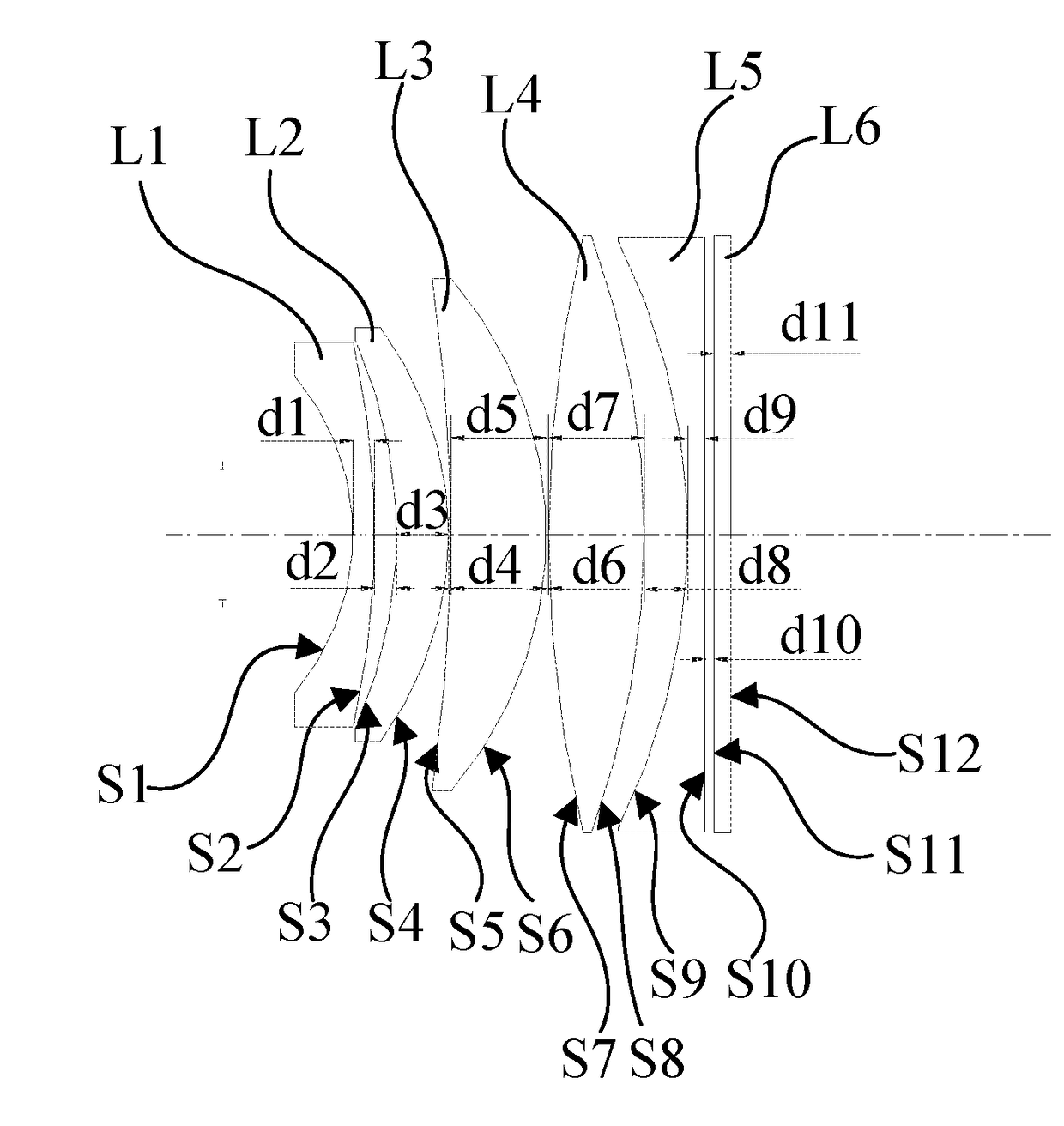
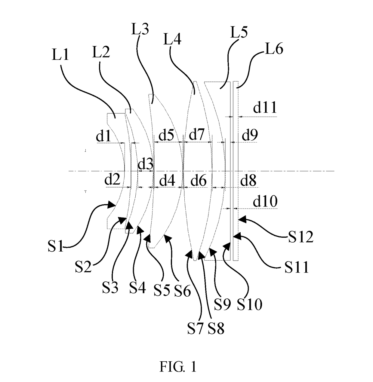
[0022]It should be noted that, in the present specification, the propagation direction of the light is from the left side to the right side of the drawing. The positive or negative curvature radius of the lens is determined by taking a relative positional relationship between an intersection point of the curved surface and the principal optical axis and a center of the spherical surface of the curved surface. If the center of the spherical surface is in the left of the intersection point, the radius of curvature has a negative value, if, on the other hand, the center of the spherical surface is in the right of the intersection point, the radius of curvature has a positive value. In addition, one side on the left of the lens is referred as the object side, and the other side on the right of the lens is referred as the image side. A positive lens is a lens in which the central...


PUM


Abstract

An optical lens comprising a first lens (L1), a second lens (L2), a third lens (L3), a fourth lens (L4), and a fifth lens (L5) that are sequentially arranged on a common optical axis in the transmission direction of an incident light. Both the first lens (L1) and the fifth lens (L5) are negative meniscus lenses. Both the second lens (L2) and the third lens (L3) are positive meniscus lenses. The fourth lens (L4) is a biconvex lens. The optical lens is applicable in an optical system of a laser processing apparatus. When an employed processing wavelength is different from a monitoring wavelength, imaging color differences in a monitoring system can thus be eliminated, specifically, when a wavelength in the infrared range is employed as a laser processing wavelength while a red wavelength serves as the monitoring wavelength, improved imaging effects are provided in the monitoring system, thus ensuring the quality of laser processing.

Description

FIELD OF THE INVENTION[0001]The present disclosure relates to the field of optics, and more particularly relates to an optical lens applied to a laser processing.BACKGROUND OF THE INVENTION[0002]With the increasingly growing of the laser processing technology, a full monitoring of laser processing process (laser marking or laser cutting) is desired, so as to ensure the processing quality. Currently, the common monitoring method is to use CCD monitoring system to monitor the whole process. Compared with the conventional processing system in which focusing is performed with the naked eye at the beginning of processing, the CCD monitoring system can monitor the whole process. By monitoring the entire process, the parameters can be adjusted immediately in case of quality problems, thus ensuring the quality of processing.[0003]The current CCD monitoring system has a “poor” vision at the wavelength in the far infrared light, and it has a higher sensitivity of the band in the red light reg...

Claims


Application Information

Patent Timeline
IPC IPC(8): G02B13/14
CPCG02B13/14G02B13/146
Inventor LI, JIAYINGZHOU, CHAOMINGSUN, BOCHEN, YUQINGGAO, YUNFENG
Owner HANS LASER TECH IND GRP CO LTD
Why Eureka
Try Eureka