Flex roller-crimper for improved management and termination of cover crops and other plant material

a crimping machine and flex roller technology, applied in the field of flex roller crimping machine for improving management and termination of cover crops and other plant materials, can solve the problems of soil compaction, severe reduction of the ability of water to filter through the soil, and no-till practices still possess problems, so as to minimize disturbance of previously rolled materials, minimize disturbance of planter operation, and minimize the effect of disturban

Active Publication Date: 2017-07-27
UNIV OF TENNESSEE RES FOUND
View PDF12 Cites 6 Cited by
  • Summary
  • Abstract
  • Description
  • Claims
  • Application Information

AI Technical Summary

Benefits of technology

[0011]Another embodiment utilizes both the strip and row middle units attached to a frame with the purpose of broadcast terminating or manipulating cover crops, plant material, and harvest residue prior to planting a cash crop or during the act of planting a cash crop without disturbing or tilling the soil surface over the entire swath of the implement. In this embodiment, both the strip and row middle drum units are arranged in dual rows comprised of a first row and a second row. The first row of drum units of the dual row is located in front of the second row of drum units in an offset configuration. The first row of drum units of the dual row may be located slightly in front of the second row of drum units in an offset configuration. Drum units are attached to the frame and located alternately between each row so that each adjacent drum unit is located in a different row than its adjacent neighbor drum unit. One of the dual rows is comprised of the strip roller-crimper drum units that roll and crimp the area to be planted known as the planted row. The strip unit, when attached to a planter, is oriented in front of each individual planter row unit and may be oriented directly in front of each individual planter row unit. The other row of the dual rows is comprised of the row middle roller-crimper drum units that roll and crimp the row middle. The row middle unit when attached to a planter is oriented in between each individual planter row unit. Drum units are attached and arranged such that they will not contact the same areas of cover crop, plant material, or ground surface to minimize disturbance of the previously rolled material. When one roller width ends, the neighboring roller edge begins, with no such overlapping from the front, top, or back view of the implement.
[0012]The frames to which the modular flex roller crimper system can consist of but are not limited to planters to terminate and manipulate cover crop, plant material, or harvest residue simultaneously while planting the cash crop. The modular flex roller-crimper system may be bolted, fastened, or connected directly to the frame, toolbar, or planter row unit by a mounting plate. The modular flex roller-crimpers comprising a drum unit, a mounting plate, and the tensioning mechanism to apply upward or downward pressure are connected to the individual application by a parallel arm linkage system, which may be V-link or telescoping, and may also possess stalk guide separators. The rearmost portion of the arm of the V-link parallel linkage system is bolted, fastened, or connected to the mounting plate. Pivoting of the entire flex-roller crimper system is enabled by rotational capabilities of the V-link attachment point to the mounting plate. The bottom bend section of the V-link possesses a hole allowing for a shaft to be slid through from accompanying sides as well as sliding through the inside diameter of the roller mounted bearing creating an axis for the roller to rotate around. The uppermost portion of the V-link possesses a rigid connection to each side by a crossmember. In the center of the crossmember, a fastening point is located such that a tensioning system can be attached. The tensioning system most commonly consists of a pressure regulator. The pressure regulator is attached to the crossmember, fastening point on the stroke end and the mounting plate on the bore end, in which the mounting plate is attached to the planter row unit frame, on the other end, running about parallel to the ground. The positioning of the pressure regulator at its two fastening points allows for tensioning mechanism to run parallel to the ground surface. This positioning of the pressure regulator eliminates disruption of normal functions of the attached implement, such as a planter. By pushing rearwards against the direction of movement, no force is applied upward or downward to the primary implement, such as a planter, minimizing the effect to planter operation that would be caused by the pressure regulator being run perpendicular to the ground. The pressure regulator creates either free-floating, downward, or upward tension of the roller drum unit against the plant material and ground, providing a medium for the drum unit to adjust in height position based upon topography with consistent desired pressure. The pressure regulator may also be fully contracted to lift the roller drum unit from the ground to be positioned into a storage mode. The telescoping parallel linkage consists of a mounting plate with fixed, rigid open channels protruding frontward away from the frame in which it is attached at a 15°-60° degree angle. The parallel arms, which are connected to the drum roller on the frontward end, telescope into the open channels of the mounting plate. The channels possess open slots, such that a stop bolt, pin, or fastener is inserted into to the telescoping parallel arms after they have been positioned within the open channel from the side, acting as a guide for the telescoping movement of the parallel arms that prevents the arms from sliding out of the open channels when fully extended. The two adjacent parallel arms have a fixed upward beam, connecting both arms by means of a crossmember. A pressure regulator is attached to the mounting plate on the bore side and the crossmember on the stroke side. The pressure regulator mediates pressure as the roller unit adjust in height depicted by the topography of the ground in which it contacts. As the roller drum moves upward, the parallel arms slidably retract within the inside of the open channels of the mounting plate. As the roller drum moves downward, the parallel arms slidably extend outward of the open channels. The pressure regulator is fixed in an angular position such that it is parallel to the ground surface. The pressure regulator creates surface tension of the roller drum against the plant material and ground in which it contacts. The pressure regulator extends, causing the telescoping parallel arms to extend in the event the roller drum would need to be lowered, conversely, the regulator retracts, causing the telescoping arms to retract when the roller drum would need to be raised. This allows for an adjustable pressure medium, such that an established desired force is constantly acting upon the plant material and ground surface by the roller drum unit regardless of plant density, topography, etc. By positioning the pressure regulator parallel to the ground surface, resisted force created by the roller drum traversing across varying terrain is applied in a rearward motion, which does not affect the main implement, such as a planter. By regulating resisted force frontward and rearward, in comparison to upward and downward, no effect on the implement, such as a planter row unit which is placing seeds in the ground at a specific set depth requirement, is created. The pressure regulator may also be fully contracted to lift the roller drum unit from the ground to be positioned into a storage mode. The tensioning device may be a pressure regulator such as a hydraulic cylinder, pneumatic cylinder, an air cylinder or an actuator and cylinder. Stalk guide separators may be bolted, fastened, welded, or attached to the respective parallel arms at the bottom area near the drum unit shaft hole. Stalk guide separators are advantageous in the event the user would like to guide cover crop or plant material into the area of the roller drum unit for increased contact and minimize disturbance during the rolling and crimping. Stalk guide separators trajectory is frontward and depending on application may be rotated by adjustments to be set at the appropriately desired angle.

Problems solved by technology

However, no-till practices still possess issues.
Since the fields are not tilled, soils become compacted, which severely reduces the ability of water to filter through the soil.
In turn, soil compaction reduces crop yield.
Water runoff not only results in unused water, it also moves residual pesticides away from the targeted area and causes soil erosion.
Also, due to the heavy reliance on herbicides to manage undesirable plants, some of these plants have acquired herbicide resistance, making them both challenging and costly to manage.
Although cover crops offer many attractive benefits, inefficient methods of termination are slowing their adoption rate.
However, in some scenarios, such as organic farming, herbicides may not be an option.
It is used to roll over and press cover crops or plant material and evenly crimp or pinch the stems of the plants, preventing translocation of water and nutrients, resulting in termination of the plant.
However, current commercial roller-crimpers over 15 feet in length require an individual pass to be made to roll and crimp the cover crop before the planter is able to sow seed of the desired cash crop.
However, current roller-crimpers are not effective on uneven surfaces and slopes, because the roller-crimper is unable to make uniform contact with the ground unless the surface is perfectly flat.
Also, current roller-crimpers do not allow a grower to leave living cover crops or plant biomass in between the planted rows of the cash crop.
The ability to quickly adjust pressure as needed is not available.

Method used


Image

  • Flex roller-crimper for improved management and termination of cover crops and other plant material
  • Flex roller-crimper for improved management and termination of cover crops and other plant material
  • Flex roller-crimper for improved management and termination of cover crops and other plant material

Examples


Embodiment Construction

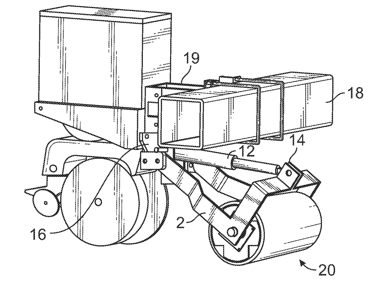
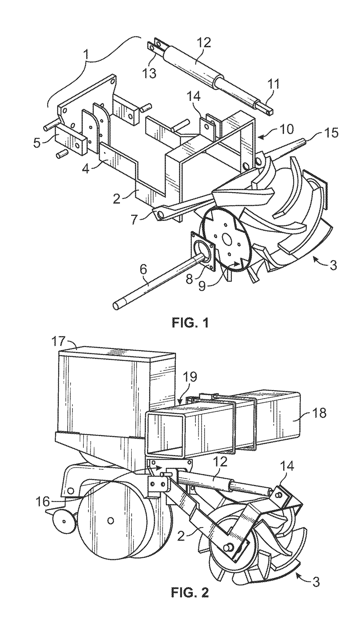
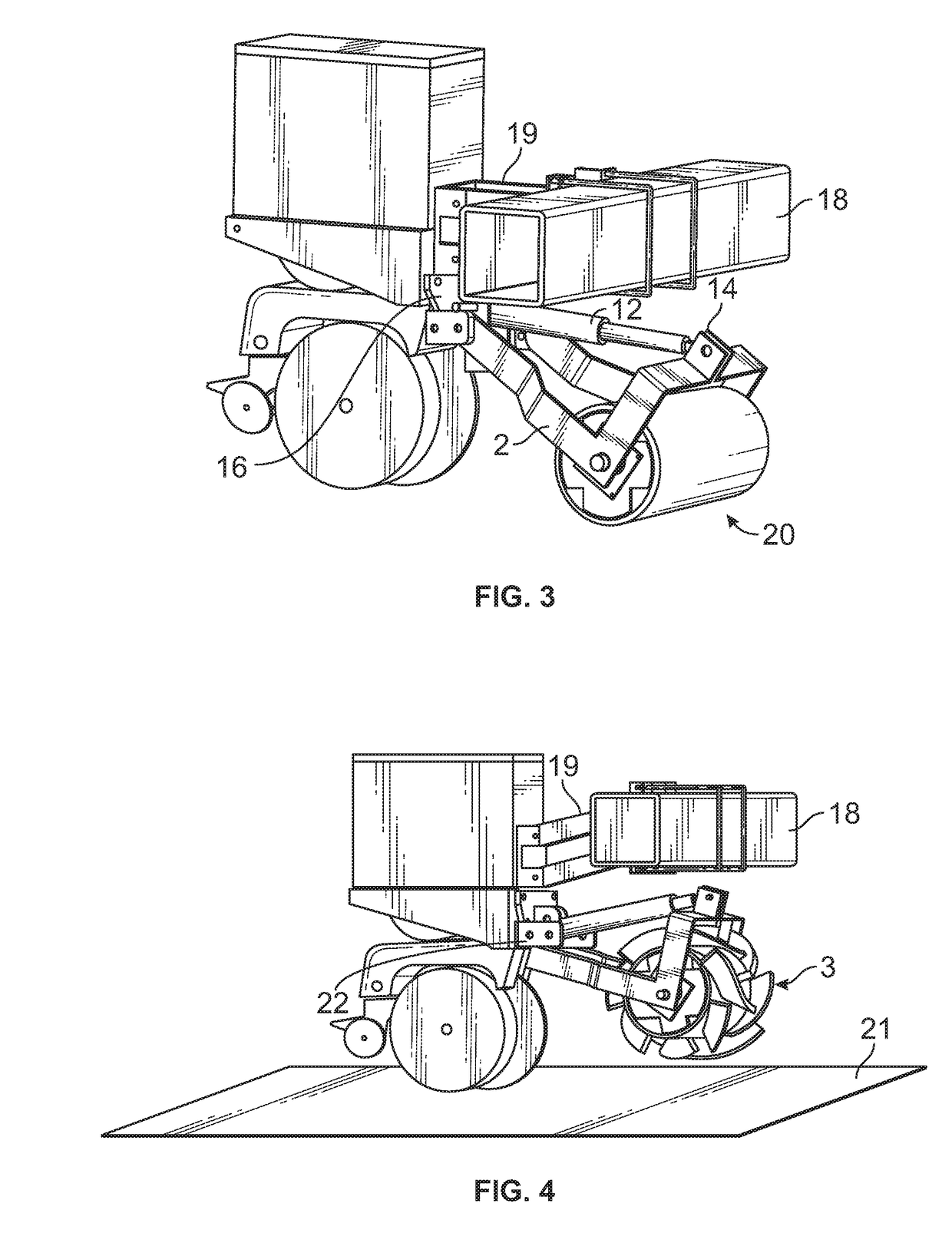
[0035]It should be understood that the present disclosure is to be considered as an exemplification of the present invention, and is not intended to limit the invention to the specific embodiments illustrated. It should be further understood that the title of this section of this application (“Detailed Description of the Invention”) relates to a requirement of the United States Patent Office, and should not be found to limit the subject matter disclosed herein. References made to certain directions such as “front” and “rear” are made as viewed from the frontward or rearward perspective of the flex roller-crimper system. References made to “planted row” are viewed as the area in which seeds are sewn in a line forming a row. References made to “row middle” are viewed as the areas in between two planted rows in which seeds are sewn in a line. References made to “strip unit” are describing the flex roller crimper system attached to a planter row unit, traversing over the planted row. Re...


PUM


Abstract

Herein is described an agricultural device that can include a frame; and a plurality of roller-crimping devices supported by the frame arranged in at least one row oriented in a direction that is transverse to a direction of travel of the agricultural device. Each of the plurality of roller-crimping devices having an exterior surface configured to at least partially crush stems of residual plant matter, and being individually movably mounted to the frame such that each of the plurality of roller-crimping devices will move at least vertically with respect to the frame when subjected to a temporary increase in resistance caused by an encounter with a non-uniform region in the field.

Description

TECHNICAL FIELD[0001]This invention relates to agricultural devices, more directly relating to field preparation for planting or sowing cash crops in no-tillage cropping systems where cover crops, undesirable plants, or plant residue exist by means of an improved modular apparatus for roller-crimping.BACKGROUND OF THE INVENTION[0002]Since the development of “no-till” farming, researchers, consultants, and growers have adopted the practice for its economic and environmental benefits. “No-till” practices consist of managing cash crops with minimal to no tillage used, and inversely relies on herbicides to manage undesirable plants. No-till farming offers many positives, such as reducing erosion, water runoff, as well as fuel, time, and labor costs. However, no-till practices still possess issues. Since the fields are not tilled, soils become compacted, which severely reduces the ability of water to filter through the soil. In turn, soil compaction reduces crop yield. In areas in which ...

Claims


Application Information

Patent Timeline
Patent Type & Authority Applications(United States)
IPC IPC(8): A01B39/08A01B29/04A01B29/02A01B63/00
CPCA01B39/08A01B29/02A01B29/045A01B63/008A01B29/00A01B61/046A01C7/006Y02P60/20
Inventor BUTLER, SHAWN
Owner UNIV OF TENNESSEE RES FOUND
Why Eureka
Try Eureka