Process for forming a high loft, nonwoven web exhibiting excellent recovery

a technology of nonwoven webs and high lofts, applied in the field of process forming a high loft, nonwoven webs exhibiting excellent recovery, can solve the problems of affecting the quality of finished webs, unable to recover to their original thickness, and webs tending to become hard and/or stiff, and achieve excellent recovery

Active Publication Date: 2017-07-27
BIAX FIBERFILM CORP
View PDF4 Cites 8 Cited by
  • Summary
  • Abstract
  • Description
  • Claims
  • Application Information

AI Technical Summary

Benefits of technology

[0005]Briefly, this invention relates to a process for making a high loft, non-woven web exhibiting excellent recovery.
[0008]A process for forming a high loft, non-woven web is also taught which has a 3-dimensional structure with fibers oriented in the x, y and z directions. The process includes the steps of introducing a single molten polymer to a die having 2 to 20 rows of nozzles with each row containing a plurality of nozzles. The single molten polymer is emitted, ejected or extruded through the plurality of nozzles to form a plurality of filaments. Air or gas streams are then used to facilitate downward movement of the plurality of filaments. The plurality of filaments, which are transformed into a plurality of fibers, are directed towards a pair of moving surfaces located at a distance of from between about 10 cm to about 150 cm from the plurality of nozzles. A pair of heaters is also present with each heater being associated with one of the pair of moving surfaces. The pair of heaters is capable of heating the pair of moving surfaces to an elevated temperature. The elevated temperature can be below the melting temperature of the polymer. The pair of heated moving surfaces forms a convergent passage having an entry and an exit. The plurality of fibers is deposited into the entry of the convergent passage. The plurality of fibers is then routed through the convergent passage in descending travel from the entry to the exit and between the pair of heated moving surfaces in a machine direction to form a 3-dimensional structure with the fibers oriented in the x, y and z directions. The high loft, non-woven web has a fiber size distribution of from 0 μm to about 15 μm with at least about 25% of the fibers being above 4 μm. The web also has a thickness of less than about 250 millimeters and a basis weight ranging from between about 20 g / m2 to about 3,000 g / m2. A vertical cross-section of the high loft, non-woven web, when taken parallel to its machine direction, exhibits two thin outer skins, each having a thickness of less than about 2.5 millimeters, with a plurality of snugly stacked, approximately V, U, or C-shaped structures formed therebetween. Each of the approximately V, U, or C-shaped structure having an apex facing in the machine direction. The high loft, non-woven web has a recovery value ranging from between about 20% to about 99% after being compressed under a pressure of 0.25 psi for a time period of 30 minutes. The high loft, non-woven web also has a wide fiber size distribution with the larger fibers providing the unique recovery value.
[0009]The general object of this invention is to provide a process for forming a high loft, nonwoven web exhibiting excellent recovery. A more specific object of this invention is to provide a process for forming a high loft, nonwoven web with good thermal insulation and / or acoustical insulation values.
[0012]Still another object of this invention is to provide a process for forming a high loft, nonwoven web exhibiting excellent recovery such that it can be compactly shipped without losing any material properties.
[0013]Still further, an object of this invention is to provide a process for forming a high loft, nonwoven web exhibiting from between about 40% to about 97% recovery after compression.

Problems solved by technology

Because of this, the finished web tends to lack recovery once it is compressed.
This presents an issue when such finished webs need to be rolled up or stacked for transport by truck or rail to a distance manufacturing facility.
If the webs are compacted or compressed during shipment, they lack the ability to recovery to their original thickness.
In addition, once compacted or compressed, such webs tend to become hard and / or stiff and their pore structure may become less open.
Furthermore, the drapeability of such webs can be diminished.
Functionally, if a compacted or compressed web cannot recovery to approximately its initial loft thickness after shipment, it can lose some of its thermal and / or acoustical insulation properties, thereby rendering the material less than desirable for this purpose.

Method used


Image

  • Process for forming a high loft, nonwoven web exhibiting excellent recovery
  • Process for forming a high loft, nonwoven web exhibiting excellent recovery
  • Process for forming a high loft, nonwoven web exhibiting excellent recovery

Examples


example 1

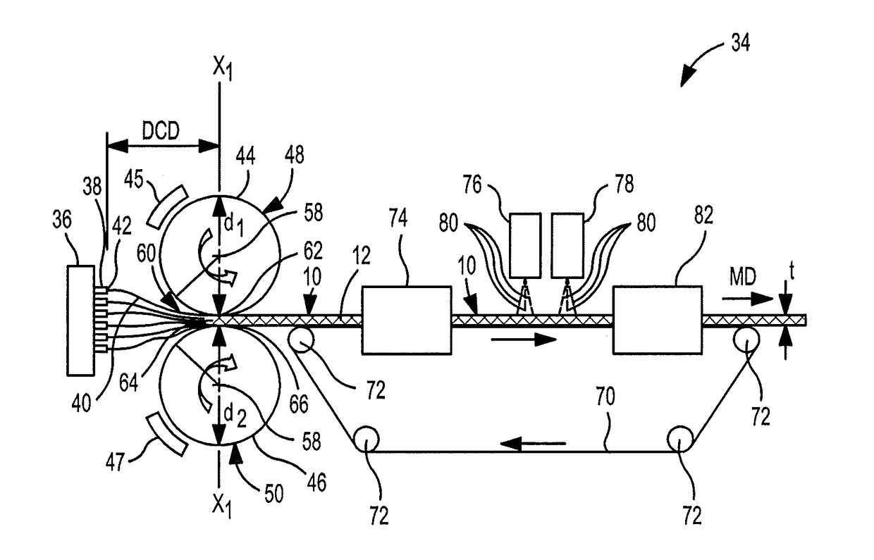
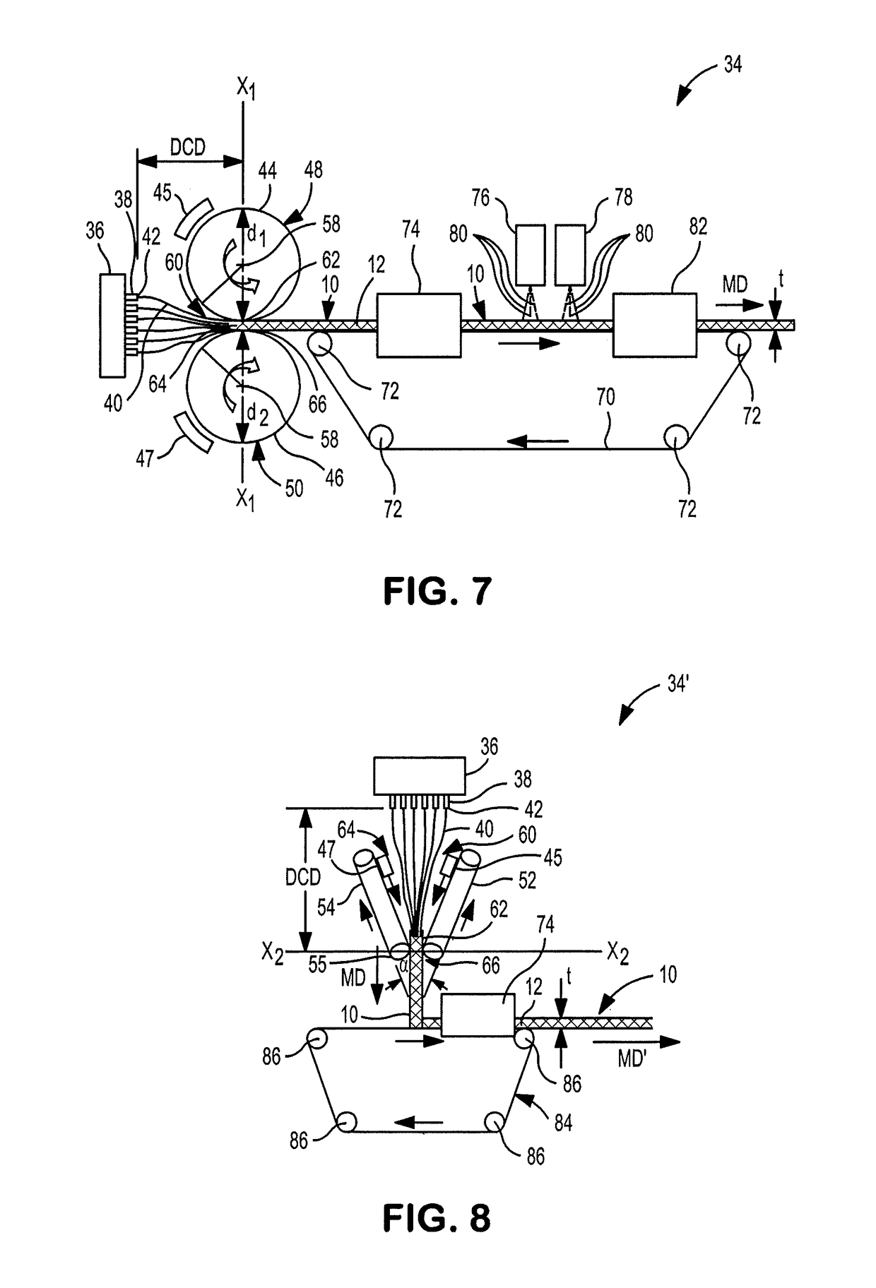
[0052]In this example, we were looking at the effect of spinning technology on web properties. Three (3) different non-woven webs were made using polypropylene resin. All three (3) had the same basis weight but each was spun using a different spinnerette design and different processing conditions. As shown in Table 1, sample S-1 was produced using a Biax multi-row spinnerette design that did not have air insulation inserts or an air shrouding curtain surrounding the periphery of the nozzles 38. Sample S-2 was produced using a conventional meltblown process which had only one line of nozzles along with inclined air jets. Sample S-3 was produced using the inventive process.

[0053]The sample S-3 achieved almost double the machine direction (MD) tensile strength as compared to sample S-1 or sample S-2. Also, one will notice that the fiber diameter of sample S-3 was slightly larger than the fiber diameter of the conventional meltblown sample S-2. The primary reason for this difference in ...

example 2

[0059]In this second example, we were comparing a sample produced by the inventive process S-5 to a sample produced by a conventional meltblown process S-4, and to a sample produced by a conventional spunbond process S-6. Three (3) samples were made and each had the same basis weight. As shown in Table 2, the properties of sample S-5 were about half-way between the properties of the conventional meltblown web S-4 and the conventional spunbond web S-6. Table 2 also shows that the air permeability of the sample S-5 (using our inventive process) falls almost half-way between the conventional meltblown sample S-4 and the conventional spunbond sample S-6. This proves that our new technology is capable of producing non-woven webs that have fine fiber diameters, comparable to meltblown fibers, yet still have strong fibers when compared to spunbond fibers.

[0060]Referring to FIG. 10, the machine direction (MD) tensile strength of the non-woven web 10, 10′, 10″ or 11 of this invention (sample...


PUM

PropertyMeasurementUnit
distanceaaaaaaaaaa
pressureaaaaaaaaaa
thicknessaaaaaaaaaa

Abstract

A process for forming a high loft, nonwoven web is disclosed. The process includes introducing a single molten polymer to a die having a plurality of nozzles. Emitting the molten polymer through the nozzles to form a plurality of filaments. Using air streams to facilitate movement and drawing of the filaments. Directing the filaments, which are transformed into fibers, towards a pair of heated moving surfaces. The pair of heated moving surfaces forming a convergent passage having an entry and an exit. Depositing the fibers into the entry of the convergent passage and routing the fibers between the pair of heated moving surfaces in a machine direction to form a high loft, non-woven web. The web having a fiber size distribution of from 0 μm to about 15 μm with at least about 25% of the fibers being above 4 μm.

Description

CROSS-REFERENCE TO RELATED APPLICATION[0001]This application is a Continuation-In-Part of non-provisional application Ser. No. 14 / 167,488, filed Jan. 29, 2014, which is incorporated herein by reference in its entirety.FIELD OF THE INVENTION[0002]This invention relates to a process forming a high loft, non-woven web exhibiting excellent recovery, especially a web formed from a single polymer and using a single “Spun-Blown®” die.BACKGROUND OF THE INVENTION[0003]Typically, polymeric fibers, formed by spunbonding, meltblowing or by some other extrusion process are collected downstream from an emitter, such as a die with a plurality of nozzles, on a horizontal oriented conveyor belt. Such processes tends to produce two-dimensional web where the fibers are oriented in the x and y directions since they are laid down in a horizontal plane. There are few if any fibers within the formed web that are oriented in the z-direction. Because of this, the finished web tends to lack recovery once it ...

Claims


Application Information

Patent Timeline
Patent Type & Authority Applications(United States)
IPC IPC(8): D04H1/559D04H5/08B29C47/00D01D5/26D04H1/552D04H1/58D04H1/56D04H3/02B29C48/05
CPCD04H1/559D04H1/56D04H5/08D04H3/02B29L2007/008D04H1/552D04H1/58B29C47/0014B29C47/0064D01D5/26D04H1/74D04H3/16D04H1/407B29C48/05B29C48/0021
Inventor BROWN, DOUGLAS BSTARK, JEFFREY DHASSAN, MOHAMMAD A.
Owner BIAX FIBERFILM CORP
Why Eureka
Try Eureka