
Devices and methods for sensing targets using photothermal speckle detection

Active Publication Date: 2017-07-27
MASSACHUSETTS INST OF TECH
View PDF4 Cites 10 Cited by
  • Summary
  • Abstract
  • Description
  • Claims
  • Application Information

AI Technical Summary

Benefits of technology

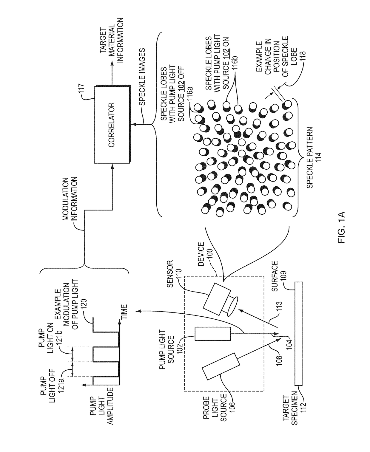
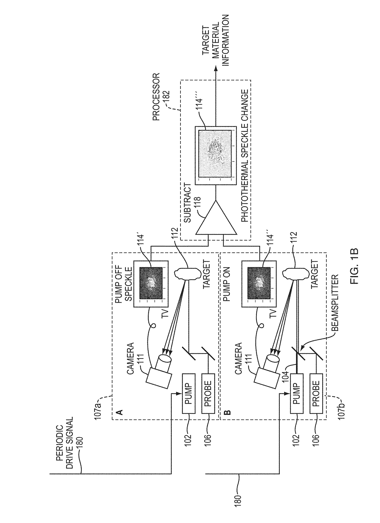
The patent text describes a new technique for non-contact analysis of target materials using infrared light. The technique is high-sensitivity, non-contact detection of target materials without the need for cryogenic temperatures or expensive cryogenic sensors. It uses two wavelengths of pump light and a probe light to create a speckle pattern that is analyzed to identify material properties such as absorption spectra and thermal diffusivity. The technique can be used in remote sensing of target materials and can identify materials based on their absorption spectra, even when the pump light is absorbed by the surface of the target material. The sensor can detect changes in the position and intensity of speckle lobes caused by the pump light modulation and can identify materials based on the correlation of the changes with the pump modulation. The technique can be used with different types of detectors and can be implemented in a compact device.

Problems solved by technology

Existing techniques for non-contact analysis of target materials suffer from a variety of drawbacks.
Some of these drawbacks include the difficulty, expense, atmospheric absorption, and detector noise associated with detecting long-wavelength infrared (LWIR) light.
Other disadvantages include the complexity of interpreting scattering spectra, limited spatial resolution and signal-to-noise ratios (SNRs), and limited sensitivity.

Method used


Image

  • Devices and methods for sensing targets using photothermal speckle detection
  • Devices and methods for sensing targets using photothermal speckle detection
  • Devices and methods for sensing targets using photothermal speckle detection

Examples


Embodiment Construction

[0053]A description of example embodiments of the invention follows.

[0054]The current disclosure describes methods and devices for obtaining optical absorption information for materials on surfaces in a non-contact manner using laser illumination. Embodiments can be used for detecting contamination of surfaces with hazardous materials (e.g. explosives or chemical warfare agents) or for doing material identification (e.g., of paints or other coatings). Embodiment devices and methods can also be used to nondestructively test surfaces for variation in optical absorption, thermal diffusivity, and to detect subsurface features that cause variation in the response of the surface to the absorption of illuminating radiation.

[0055]Embodiments can take advantage of photothermal modulation of a laser speckle pattern emanating from a surface of a target specimen, which is also referred to herein as “photothermal speckle modulation” (PSM). The approach can include simultaneous illumination of th...


PUM


Abstract

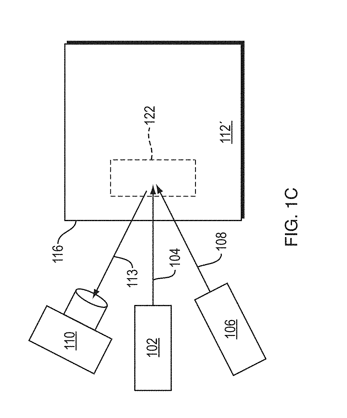
A device, and corresponding method, can include a pump light source configured to be modulated at a pump modulation and to irradiate a target specimen. The device can also include a probe light source arranged to generate a speckle pattern from the target specimen, as well as a sensor configured to detect changes in at least one of position and intensity of one or more speckle lobes of the speckle pattern having correlation with the pump modulation. The device and method can be used for non-contact monitoring and remote sensing of surfaces, gases, liquids, particles, and other target materials by analyzing speckle pattern changes as a function of pump light irradiation. Advantages can include much higher sensitivity than existing methods; the ability to use visible probe wavelengths for uncooled, low-cost visible detectors with high spatial resolution; and the ability to obtain target material properties without detecting infrared light.

Description

RELATED APPLICATIONS[0001]This application claims the benefit of U.S. Provisional Application No. 62 / 207,720, filed on Aug. 20, 2015. The entire teachings of the above application(s) are incorporated herein by reference.GOVERNMENT SUPPORT[0002]This invention was made with government support under FA8721-05-C-0002 from the AirForce Life Cycle Management Center and under FA8721-05-C-0002 from the Department of Defense Research and Engineering Enterprise. The government has certain rights in the invention.BACKGROUND[0003]Various techniques have been used for non-contact sensing of target materials. One class of existing techniques can be referred to as reflectance spectroscopy. Infrared (IR) reflectance spectroscopy directly detects back-scattered radiation at the pump wavelength, which can also be used to determine optical properties of the target material surface.[0004]A second class of techniques that probe infrared absorption of target materials are alternative photothermal approac...

Claims


Application Information

Patent Timeline
IPC IPC(8): G01J3/433G01J3/10G01J3/28G01J3/447
CPCG01J3/433G01J3/2823G01J3/108G01J3/447G01N21/1717G01N21/636G01N2021/1725
Inventor JEYS, THOMAS H.HERZOG, WILLIAM D.SAAR, BRIAN G.STOLYAROV, ALEXANDER M.SULLENBERGER, RYANCROMPTON, DAVIDREDMOND, SHAWN MICHAEL
Owner MASSACHUSETTS INST OF TECH
Learn More