Pressure-type flow rate control device

a flow rate control and flow rate technology, applied in the direction of diaphragm valves, valve housings, instruments, etc., can solve the problems of difficult to significantly low gas replaceability, and low so-called gas shutoff responsiveness, so as to improve the shutoff response characteristics and reduce the distance between the control valve for pressure control and the on/off valve , the effect of improving the shutoff characteristics

Active Publication Date: 2017-07-27
FUJIKIN INC
View PDF4 Cites 8 Cited by
  • Summary
  • Abstract
  • Description
  • Claims
  • Application Information

AI Technical Summary

Benefits of technology

[0058]In the present invention, a control valve for pressure control is fixed in a horizontal position to a main body provided with a fluid passage, and also an on / off valve is fixed in a vertical position. Accordingly, the distance between the control valve for pressure control and the on / off valve can be reduced, whereby the internal volume of the fluid passage between the control valve for pressure control and an orifice provided on the upstream side of the on / off valve can be made smaller than before. As a result, the shutoff characteristics can be improved.
[0059]In the present invention, to a main body provided with a fluid passage, a control valve for pressure control and an on / off valve are fixed in a horizontal position to be opposed to each other. Accordingly, the distance between the control valve for pressure control and the on / off valve can be reduced, whereby the internal volume of the fluid passage between the control valve for pressure control and an orifice provided on the upstream side of the on / off valve can be made smaller than before. As a result, the shutoff characteristics can be improved.
[0060]In the present invention, the on / off valve and the orifice are formed as an orifice-built-in valve having the orifice integrally assembled and fixed in the on / off valve. Accordingly, further downsizing of the pressure-type flow controller can be achieved, whereby the internal volume of the fluid passage can be made even smaller.
[0061]In the present invention, the pressure sensor for detecting the internal pressure of the fluid passage between the control valve for pressure control and the orifice includes a pressure introducing pipe projecting outward from the casing of the pressure sensor, and a tip portion of the pressure introducing pipe is air-tightly attached to the main body. Accordingly, the space for attaching the pressure sensor to the main body can be small, and the distance between the control valve for pressure control and the orifice can be further reduced, whereby the internal volume of the fluid passage can be further minimized.
[0062]In the present invention, the fourth passage portion is connected to an end portion of the pressure sensing chamber on the control valve for pressure control side, while the fifth passage portion is connected to an end portion of the pressure sensing chamber on the on / off valve side. Accordingly, the length of the fourth passage portion and that of the fifth passage portion can be shortened, and, as a result, the internal volume of the fluid passage between the control valve for pressure control and the orifice provided on the upstream side of the on / off valve can be minimized.
[0063]In the present invention, the cross-sectional shapes of the first passage portion, the second passage portion, and the third passage portion of the fluid passage, those of the horizontal passage portion and the vertical passage portion of the fluid passage, and those of the passage portion and the fifth passage portion are each a circular shape having an inner diameter of 0.5 mm to 1.0 mm. Accordingly, the internal volume of the fluid passage can be further minimized.

Problems solved by technology

However, in a pressure-type flow controller FCS of this kind, because an orifice OL having a fine bore diameter is used, the gas replaceability is low.
Thus, in the case where the control valve for pressure control CV of the pressure-type flow controller FCS is closed to open the output side, it takes a long period of time to exhaust the gas in the space part between the control valve CV and the orifice OL, leading to a problem in that the so-called gas shutoff responsiveness is extremely low.
However, even with the pressure-type flow controller shown in FIG. 10, it is difficult to significantly improve the shutoff response characteristics, and the problem of poor shutoff response characteristics in conventional pressure-type flow controllers still left unsolved.

Method used


Image

  • Pressure-type flow rate control device
  • Pressure-type flow rate control device
  • Pressure-type flow rate control device

Examples


first embodiment

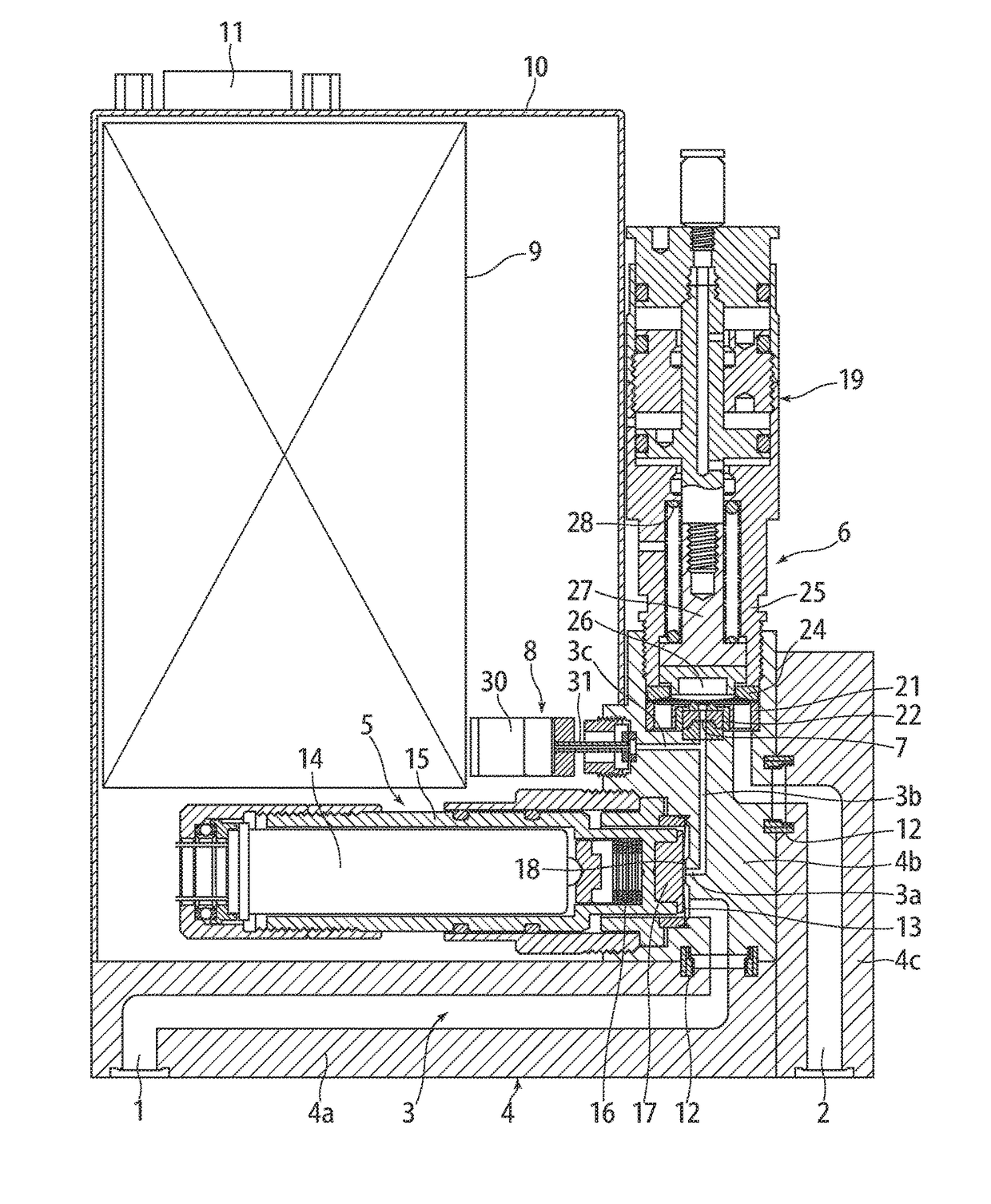
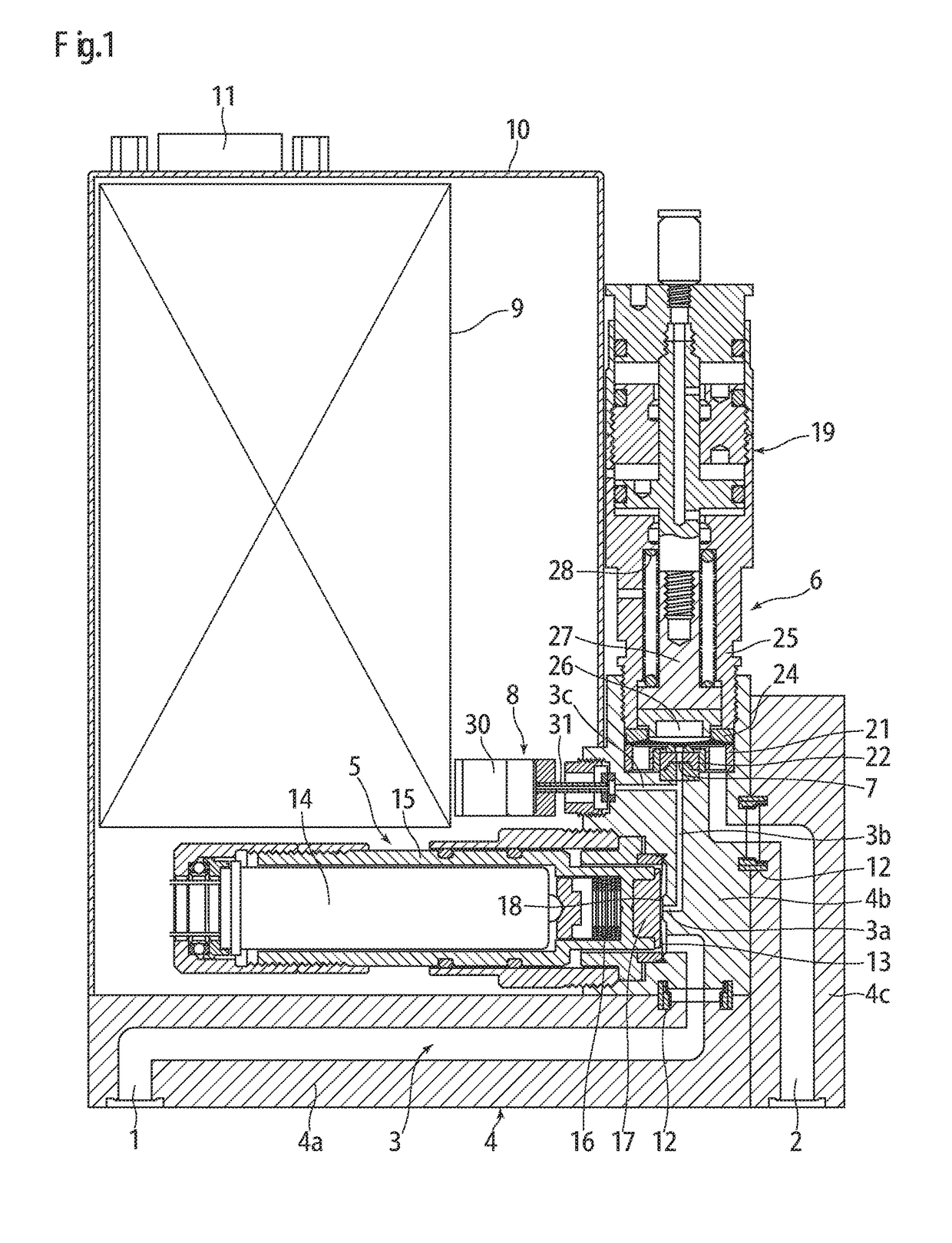
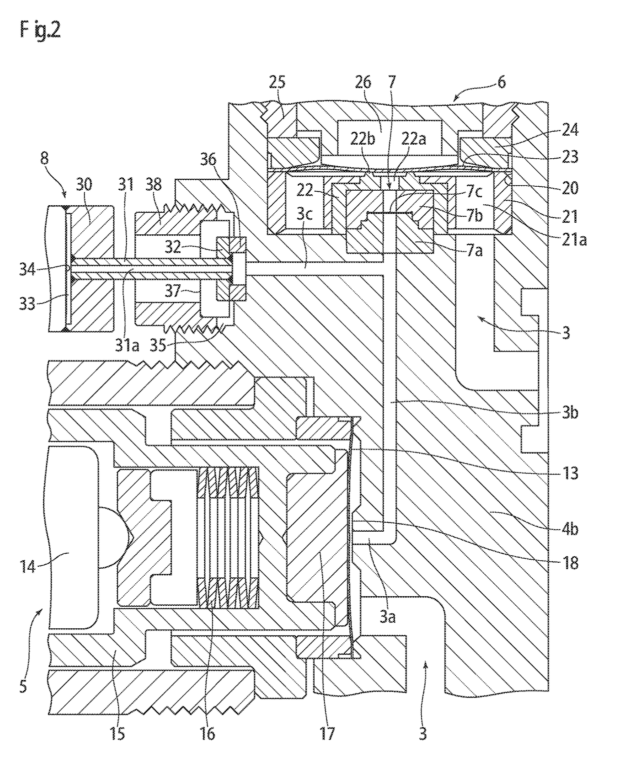
[0076]FIG. 1 and FIG. 2 show a pressure-type flow controller according to the present invention. The pressure-type flow controller includes: a main body 4 provided with a fluid passage 3 communicating between a fluid inlet 1 and a fluid outlet 2; a control valve for pressure control 5 fixed in a horizontal position to the main body 4 for opening / closing the fluid passage 3; an on / off valve 6 fixed in a vertical position to the main body 4 for opening / closing the fluid passage 3 on the downstream side of the control valve for pressure control 5; an orifice 7 provided in the fluid passage 3 on the upstream side of the on / off valve 6; and a pressure sensor 8 fixed to the main body 4 for detecting the internal pressure of the fluid passage 3 between the control valve for pressure control 5 and the orifice 7. The fluid passage 3 includes: a first passage portion 3a in a horizontal position connected to the control valve for pressure control 5; a second passage portion 3b in a vertical po...

second embodiment

[0100]FIG. 4 and FIG. 5 show a pressure-type flow controller according to the present invention. The pressure-type flow controller includes: a main body 4 provided with a fluid passage 3 communicating between a fluid inlet 1 and a fluid outlet 2; a control valve for pressure control 5 fixed in a horizontal position to the main body 4 for opening / closing the fluid passage 3; an on / off valve 6 fixed to the main body 4 to be opposed to the control valve for pressure control 5 for opening / closing the fluid passage 3 on the downstream side of the control valve for pressure control 5; an orifice 7 provided in the fluid passage 3 on the upstream side of the on / off valve 6; and a pressure sensor 8 fixed to the main body 4 for detecting the internal pressure of the fluid passage 3 between the control valve for pressure control 5 and the orifice 7. The fluid passage 3 includes: a horizontal passage portion 3d connecting between the control valve for pressure control 7 and the orifice 7; and a...

third embodiment

[0118]FIG. 6 shows a pressure-type flow controller according to the present invention. In the pressure-type flow controller, a fluid inlet 1 and a fluid outlet 2 are formed on the same surface of a main body 4 (upper surface of the main body 4 shown in FIG. 6) such that the fluid inlet 1 and the fluid outlet 2 are arranged in one direction on the main body 4. At the same time, a pressure sensor 8 is provided at a central position of the surface of the main body 4 on the opposite side of the fluid inlet 1 and the fluid outlet 2 (lower surface of the main body 4 shown in FIG. 6).

[0119]Except that the fluid inlet 1 and the fluid outlet 2 are formed on the same surface of the main body 4, and that the pressure sensor 8 is provided at the central position of the opposite surface of the main body 4, the pressure-type flow controller according to the third embodiment is configured to have the same structure as the pressure-type flow controller according to the second embodiment shown in FI...


PUM


Abstract

The pressure-type flow controller includes a main body provided with a fluid passage, a control valve for pressure control fixed in a horizontal position to the main body, an on/off valve fixed in a vertical position to the main body on the downstream side of the control valve for pressure control, an orifice provided in the fluid passage on the upstream side of the on/off valve, and a pressure sensor fixed to the main body for detecting the internal pressure of the fluid passage between the control valve for pressure control and the orifice. The fluid passage includes a first passage portion in a horizontal position connected to the control valve for pressure control, a second passage portion in a vertical position connecting the first passage portion to the orifice, and a third passage portion in a horizontal position connecting the second passage portion to the pressure sensor.

Description

TECHNICAL FIELD[0001]The present invention relates to the improvement of a pressure-type flow controller interposed in a fluid supply line of a semiconductor manufacturing device or the like to control the flow rate of a fluid (gas). It particularly relates to a pressure-type flow controller having enhanced shutoff response characteristics, thereby allowing for significant enhancement of the operation performance of a source gas supply device for a semiconductor manufacturing device or the like.BACKGROUND ART[0002]Conventionally, in source gas supply devices for semiconductor manufacturing devices and the like, thermal type flow controllers and pressure-type flow controllers have been widely used for controlling the supplied gas flow. In particular, a pressure-type flow controller FCS shown in FIG. 8 is composed of a control valve for pressure control CV, a temperature detector T, a pressure sensor P, an orifice OL, a computation control unit CD including a temperature correction / fl...

Claims


Application Information

Patent Timeline
Patent Type & Authority Applications(United States)
IPC IPC(8): G05D7/06
CPCG05D7/0635Y10T137/776F16K7/12F16K27/0236G05D7/06
Inventor NAGASE, MASAAKIHIRATA, KAORUDOHI, RYOUSUKENISHINO, KOUJIIKEDA, NOBUKAZU
Owner FUJIKIN INC
Why Eureka
Try Eureka