Receiving Antenna and Wireless Power Receiving Appartus Comprising Same

a technology of receiving antenna and receiving apparatus, which is applied in the direction of loop antennas with ferromagnetic cores, non-resonant long antennas, magnetic bodies, etc., can solve the problems of reducing the guiding effect of soft magnetic layers, and achieve the goal of maximizing the receiving efficiency, improving the focusing performance of electromagnetic energy, and improving the efficiency of the receiving antenna

Active Publication Date: 2017-07-27
SCRAMOGE TECH LTD
View PDF3 Cites 10 Cited by
  • Summary
  • Abstract
  • Description
  • Claims
  • Application Information

AI Technical Summary

Benefits of technology

[0021]According to an embodiment of the present invention, because electromagnetic energy focusing performance of a receiving antenna can be improved in a wireless power receiving apparatus, wireless power transmitting and receiving efficiency can be maximized. Particularly, a magnetic field guiding effect of a soft magnetic layer can be improved by removing a void between a receiving coil and the soft magnetic layer, and improved power transmission efficiency can be obtained by decreasing a thickness of the receiving antenna and decreasing a distance between a transmitting antenna and the receiving antenna.
[0022]Accordingly, because a required level of electromagnetic energy focusing effect can be obtained even in small thickness, the receiving antenna is applicable to technology of various electronic devices (e.g., a television (TV), a portable terminal, a laptop, a tablet personal computer (PC), etc.) which are on the slimming trend.
[0023]Also, because the electromagnetic energy focusing performance is excellent and the cost of material is cheap, the receiving antenna is applicable to large-size application fields such as electric vehicles, subways, and electric railways.

Problems solved by technology

Here, a problem in that a magnetic field guiding effect of the soft magnetic layer is decreased may occur due to a void formed between the soft magnetic layer and the receiving coil.

Method used


Image

  • Receiving Antenna and Wireless Power Receiving Appartus Comprising Same
  • Receiving Antenna and Wireless Power Receiving Appartus Comprising Same
  • Receiving Antenna and Wireless Power Receiving Appartus Comprising Same

Examples


embodiment 1

[0103]After sequentially laminating a soft magnetic layer having a thickness of 430 μm, an adhesive layer having a thickness of 54 μm, receiving coils having a thickness of 170 μm (an angle between one side adjacent to a surface of the soft magnetic layer and two sides which meet the one side is70°), and a support film having a thickness of 25 μm in that order, the soft magnetic layer, the adhesive layer, the receiving coils, and the support film were compressed at high temperature for 30 minutes under conditions of 180, 120 kgf / cm3. Also, transmission efficiency (Tx-A1) was measured under conditions in which transmitting power wad 3.5 W, 4.0 W, 4.5 W, and 4.9 W.

embodiment 2

[0104]After sequentially laminating a soft magnetic layer having a thickness of 430 μm, an adhesive layer having a thickness of 54 μm, receiving coils having a thickness of 170 μm angle between one side adjacent to a surface of the soft magnetic layer and two sides which meet the one side is 65°), and a support film having a thickness of 25 μm in that order, the soft magnetic layer, the adhesive layer, the receiving coils, and the support film were compressed at high temperature for 30 minutes under conditions of 180, 120 kgf / cm3. Also, transmission efficiency (Tx-A1) was measured under conditions in which transmitting power was 3.5 W, 4.0 W, 4.5 W, and 4.9 W.

embodiment 3

[0105]After sequentially laminating a soft magnetic layer having a thickness of 430 μm, an adhesive layer having a thickness of 54 μm, receiving coils having a thickness of 170 μm (an angle between one side adjacent to a surface of the soft magnetic layer and two sides which meet the one side is 50°), and a support film having a thickness of 25 μm in that order, the soft magnetic layer, the adhesive layer, the receiving coils, and the support film were compressed at high temperature for 30 minutes under conditions of 180, 120 kgf / cm3. Also, transmission efficiency (Tx-A1) was measured under conditions in which transmitting power was 3.5 W, 4.0 W, 4.5 W, and 4.9 W.


PUM

PropertyMeasurementUnit
angleaaaaaaaaaa
angleaaaaaaaaaa
angleaaaaaaaaaa

Abstract

A receiving antenna of a wireless power receiving apparatus for wireless power charging according to one embodiment of the present invention comprises: a substrate; a soft magnetic layer disposed on the substrate; and a receiving coil which is wound in parallel with a plane of the soft magnetic layer and is embedded on one surface of the soft magnetic layer, wherein at least one surface of the receiving coil is slantly embedded on the one surface of the soft magnetic layer.

Description

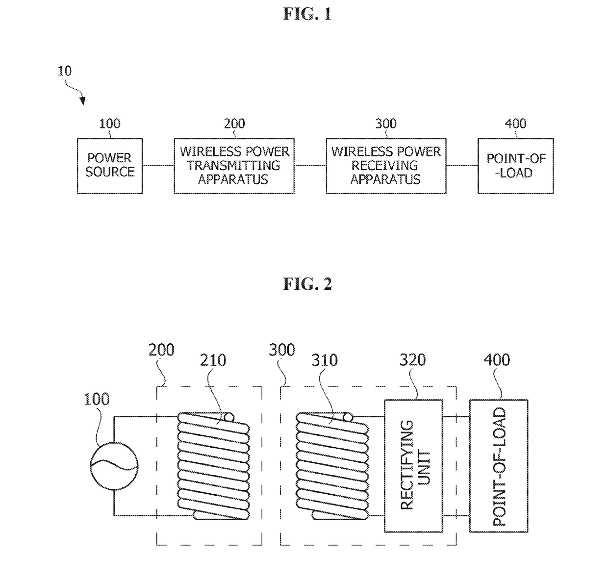
TECHNICAL FIELD[0001]The present invention relates to wireless charging, and more particularly, to a receiving antenna for wireless charging and a wireless power receiving apparatus including the same.BACKGROUND ART[0002]With development of wireless communication technology, there has been increased interest in wireless power transmitting and receiving technology for wirelessly supplying power to an electronic device. The wireless power transmitting and receiving technology can be applied for various purposes including power supply to electronic products for home use and power supply to electric vehicles or subways as well as battery charging of a portable terminal.[0003]General wireless power transmitting and receiving technology uses a principle of magnetic induction or magnetic resonance. For example, when electrical energy is applied to a transmitting antenna of a wireless power transmitting apparatus, the transmitting antenna may convert the electrical energy into electromagnet...

Claims


Application Information

Patent Timeline
Patent Type & Authority Applications(United States)
IPC IPC(8): H01F38/14H02J7/02H01F1/147H02J50/10H01F27/255H01F27/28H02J5/00H01F1/12H01F1/153
CPCH01F38/14H01F1/12H02J7/025H01F1/14725H02J50/10H01F1/15316H01F27/255H01F27/28H02J5/005H01F1/15308H01F27/306H01F27/366H01Q11/08H01F27/2871H01Q7/08H02J50/005H02J50/70H01F27/36H02J50/27H01Q1/38H01Q7/06H04B5/0037H04B5/0081
Inventor LEE, JUNG EUNLEE, SANG WONBAE, SEOKHYUN, SOON YOUNGLEE, HEE JUNG
Owner SCRAMOGE TECH LTD
Why Eureka
Try Eureka