Controller for electric motor system

a technology for electric motors and controllers, applied in control systems, power conversion systems, electrical apparatuses, etc., can solve problems such as error correction and error not being corrected while electric motors are running

Active Publication Date: 2017-07-27
DENSO CORP
View PDF2 Cites 4 Cited by
  • Summary
  • Abstract
  • Description
  • Claims
  • Application Information

AI Technical Summary

Benefits of technology

[0042]Taking into consideration a relationship between the variation in the phase current having the target phase and the variation in the inter-terminal voltage of the smoothing capacitor, in the invention, the electronic control unit specifies the target phase and thus the current sensor of which the detection signal includes an error is individually specified even when the electric motor system includes plural current sensors. For example, even when the electric motor system includes at least two current sensors which individually detects phase currents of at least two phases, the current sensor of the at least two current sensors of which the detection signal includes an error is individually specified. In addition, when a target phase is specified in the second operation mode, the electronic control unit corrects the detection value of the current sensor which has detected the phase current having the target phase such that the inter-terminal voltage matches the first reference value (for example, a variation in the inter-terminal voltage is zero). As a result, the electronic control unit can correct the detection value of the current sensor so as to exclude an influence of an error when the detection value of the current sensor includes the error.
[0043]Furthermore, the electronic control unit can specify the target phase in accordance with a generated phase voltage command signal even when a predetermined period of time passes after the electric motor system is started (for example, while the electric motor system is driven in a normal mode) as well as just after the electric motor system is started. In the second operation mode, the electronic control unit can correct the detection value of the current sensor based on the detectable inter-terminal voltage of the smoothing capacitor even when a predetermined period of time passes after the electric motor system is started as well as just after the electric motor system is started. Accordingly, even when a predetermined period of time passes after the electric motor system is started as well as just after the electric motor system is started, the electronic control unit can correct the detection value of the current sensor so as to exclude an influence of an error when the detection value of the current sensor includes the error.
[0044]In this way, according to the aspect, in both modes of the first operation mode and the second operation mode, it is possible to correct the detection value of the current sensor so as to exclude an influence of an error when the detection value of the current sensor includes the error.
[0045]That is, according to the aspect, the subject that corrects the detection signal of the current sensor is changed depending on the operation mode of the power converter. Specifically, the electronic control unit corrects the detection value such that a difference between the detection value and the second reference value is decreased when the power converter operates in the first operation mode based on the rectangular wave control mode, the inter-terminal voltage matches the first reference value, and the detection value does not match the second reference value. On the other hand, the electronic control unit corrects the detection value of the phase current having the target phase such that the inter-terminal voltage matches the first reference value when the power converter operates in the second operation mode based on the pulse width modulation control mode. As a result, even when the power converter operates in any of the first operation mode and the second operation mode, it is possible to correct a detection signal of a current sensor so as to suppress or exclude an influence of an error included in the detection signal of the current sensor.

Problems solved by technology

However, in the technique disclosed in JP 2000-023490 A, an error is corrected only just after an electric motor is started.
Accordingly, an error is not corrected while the electric motor is driven.

Method used


Image

  • Controller for electric motor system
  • Controller for electric motor system
  • Controller for electric motor system

Examples


Embodiment Construction

[0079]Hereinafter, embodiments of a controller for an electric motor system will be described. Embodiments of the controller for an electric motor system will be described using a vehicle 1 to which the controller for an electric motor system is applied. Here, the controller for an electric motor system may be applied to arbitrary equipment (particularly, arbitrary equipment including an electric motor) other than a vehicle.

[0080]The configuration of the vehicle 1 according to this embodiment will be first described below with reference to FIGS. 1 to 4.

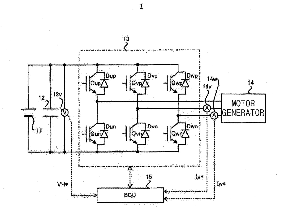
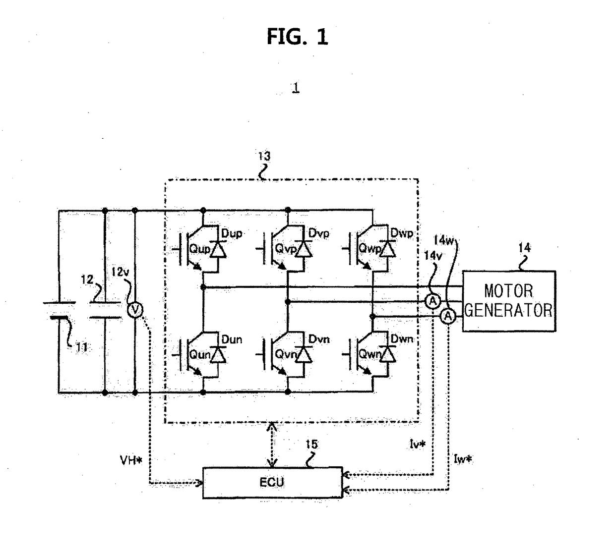
[0081]The entire configuration of the vehicle 1 according to this embodiment will be first described with reference to FIG. 1. FIG. 1 is a block diagram illustrating the entire configuration of the vehicle 1 according to a first embodiment.

[0082]As illustrated in FIG. 1, the vehicle 1 includes a DC power supply 11, a smoothing capacitor 12, a voltage sensor 12V, an inverter 13 which is an example of the “power converter”, a motor gene...


PUM


Abstract

A controller for an electric motor system is provided. The electric motor system includes a DC power supply, a power converter, a smoothing capacitor, a three-phase AC motor, and a current sensor. The controller includes an electronic control unit. The electronic control unit is configured to control the power converter such that an inter-terminal voltage of the smoothing capacitor matches a first reference value. The first reference value is a value which is determined as the inter-terminal voltage of the smoothing capacitor when a phase current is equal to a second reference value. The electronic control unit is configured to correct a detection value of the current sensor so as to decrease a difference between the detection value and the second reference value when the inter-terminal voltage matches the first reference value and the detection value does not match the second reference value.

Description

BACKGROUND OF THE INVENTION[0001]1. Field of the Invention[0002]The present invention relates to a technical field of, for example, a controller that controls an electric motor system having a three-phase AC motor.[0003]2. Description of Related Art[0004]An example of a control method of driving a three-phase AC motor is pulse width modulation (PWM) control. The PWM control is to control a power converter (for example, an inverter) that converts a DC voltage (DC power) into an AC voltage (AC power) based on a magnitude relation between a phase voltage command signal, which is set from the viewpoint of matching phase currents supplied to a three-phase AC motor with a desired value, and a carrier signal of a predetermined frequency.[0005]Another example of the control method of controlling a three-phase AC motor is rectangular wave control. The rectangular wave control is to control a power converter (for example, an inverter) that converts a DC voltage (DC power) into an AC voltage (...

Claims


Application Information

Patent Timeline
Patent Type & Authority Applications(United States)
IPC IPC(8): H02P27/08
CPCH02M7/53871H02P27/08H02P27/085
Inventor YAMAKAWA, TOSHIFUMIOKAMURA, MASAKITAKAMATSU, NAOYOSHI
Owner DENSO CORP
Why Eureka
Try Eureka