Imprint apparatus, control method, and method for manufacturing article

a technology of printing apparatus and control method, which is applied in the direction of photomechanical apparatus, instruments, other domestic objects, etc., can solve the problems of pattern defects that cannot be applied to the technology of curing inhibition, and the pattern defects that occur, so as to reduce the formation of pattern defects

Active Publication Date: 2017-08-03
CANON KK
View PDF8 Cites 1 Cited by
  • Summary
  • Abstract
  • Description
  • Claims
  • Application Information

AI Technical Summary

Benefits of technology

[0007]The present invention provides, for example, an imprint apparatus which is capable of reducing pattern defects formed on a substrate.

Problems solved by technology

If a concentration of helium is insufficient, oxygen remains in the sealing space and curing the imprint material is inhibited, and thereby pattern defects occur.
However, Japanese Patent Laid-Open No. 2011-181548 and Japanese Patent Laid-Open No. 2014-120604 disclose a technology for reducing pattern defects caused by an adhesion force generated in releasing a mold from a cured imprint material, and the technology cannot be applied to pattern defects caused by curing inhibition due to oxygen that occurs at low concentration of helium.

Method used


Image

  • Imprint apparatus, control method, and method for manufacturing article
  • Imprint apparatus, control method, and method for manufacturing article
  • Imprint apparatus, control method, and method for manufacturing article

Examples


first embodiment

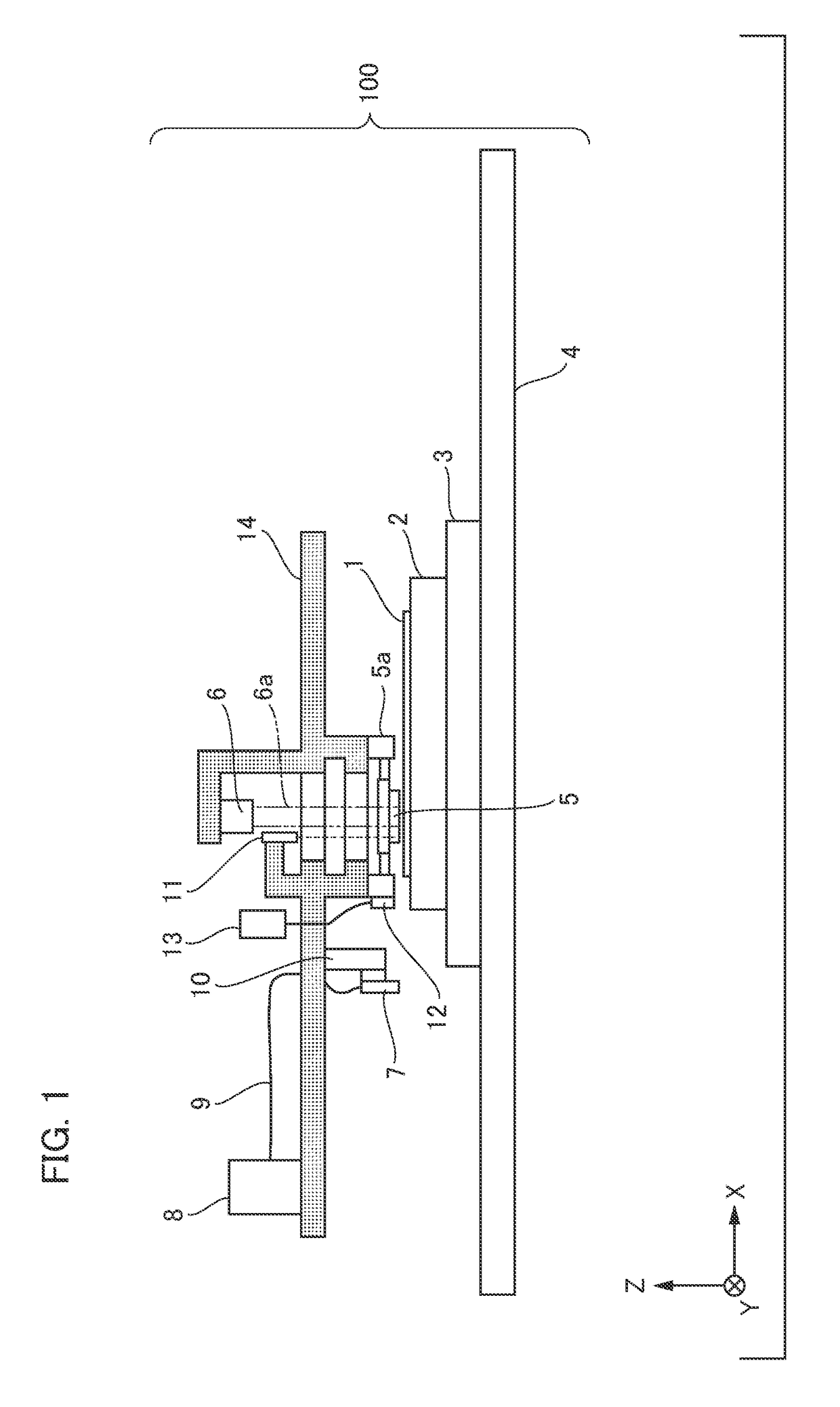
[0023]An outline of an imprint apparatus according to one embodiment of the present invention will be described with reference to FIG. 1. FIG. 1 shows an example of an apparatus configuration of the imprint apparatus. An imprint apparatus 100 of the present embodiment is configured to form a pattern in a plurality of shot areas on a substrate by repeating an imprint cycle. Here, one imprint cycle is a cycle of forming a pattern in one shot area of the substrate by curing the imprint material, in a state in which an original (mold) contacts with an uncured resin (imprint material).

[0024]In a substrate 1, an element pattern corresponding to a pattern of an original is formed on a surface layer by transferring the pattern of the original thereto. A substrate fine movement stage 2 is a stage in which the substrate 1 can be driven in an XY direction and a rotation direction in an XY plane in little amounts (about 1 mm in the XY direction, about a few degrees in the rotation direction in ...

second embodiment

[0035]FIG. 7 shows an example of a configuration of an imprint apparatus of a second embodiment. The imprint apparatus of the present embodiment further comprises a filter 18 having a transmittance distribution and a filter driving mechanism 18a in addition to the shutter 15 and the calculator 16 of Embodiment 1. The filter 18 is configured by a plurality of filters with different transmittance distributions. The calculator 16 is connected also to the filter driving mechanism 18a. The calculator 16 selects a filter in addition to the open / close times of the shutter in accordance with the amount of necessary curing light calculated based on the acquired data of the defect distribution on the substrate 1 and also issues a command for filter switching (putting the filter in / out an optical path). The filter driving mechanism 18a receives the command for filter switching from the calculator 16 and can perform filter switching to a filter selected among the plurality of filters with diffe...

third embodiment

[0038]FIG. 9 shows a configuration example of an imprint apparatus of a third embodiment. The imprint apparatus of the present embodiment comprises a light source lamp 20 and a lamp position driving mechanism 20a as a mechanism for driving a position of a lamp, in addition to the shutter 15 and the calculator 16 of the first embodiment. The lamp position driving mechanism 20a is connected to the light source lamp 20. The lamp position driving mechanism 20a is connected to the calculator 16, and is a driving unit for driving the light source lamp 20 based on a lamp position command from the calculator 16. The calculator 16 is a control unit for controlling an exposure amount of the ultraviolet light 6a, and controls the lamp position driving mechanism 20a in addition to the shutter driving mechanism 15a. Therefore, with respect to defect distributions in top, bottom, left, and right as shown in FIG. 8 of the second embodiment acquired by the calculator 16, it is possible to irradiate...


PUM

PropertyMeasurementUnit
defect distributionaaaaaaaaaa
transmittance distributionaaaaaaaaaa
transmittance distributionsaaaaaaaaaa

Abstract

An imprint apparatus for forming a pattern in an imprint material on a substrate using an original as a mold, comprises an ultraviolet light generation device which irradiates with ultraviolet light which is curing light for curing the imprint material, and a control unit which controls a light amount of the ultraviolet light which is curing light. The control unit configured to perform a control of the light amount of the ultraviolet light acquires data of a defect distribution of the pattern formed on the substrate by the mold, and performs the control of the light amount of the ultraviolet light in a plurality of shot areas on the substrate based on the acquired data of the defect distribution.

Description

BACKGROUND OF THE INVENTION[0001]Field of the Invention[0002]The present invention relates to an imprint apparatus, a control method, and a method for manufacturing an article.[0003]Description of the Related Art[0004]In an imprint technology for manufacturing a semiconductor device or the like, a pattern is formed by contacting a patterned mask onto a silicon substrate to which an imprint material is applied and curing the imprint material using ultraviolet light or heat. In the imprint technology, helium which can be transmitted through the mask and the imprint material is filled into a sealing space to prevent an air reservoir from remaining between the mask and the imprint material, in bringing the mask and the imprint material on the silicon substrate into contact. If a concentration of helium is insufficient, oxygen remains in the sealing space and curing the imprint material is inhibited, and thereby pattern defects occur. Occurrence of the pattern defects due to this curing ...

Claims


Application Information

Patent Timeline
Patent Type & Authority Applications(United States)
IPC IPC(8): B29C35/02H01L21/3105B29C59/02H01L21/67G03F7/00B29C35/08
CPCB29C35/0288G03F7/0002B29C35/0805B29C59/026H01L21/67115H01L21/67253H01L21/31058B29C2035/0827B29L2031/34H01L21/67092
Inventor MURASATO, NAOKI
Owner CANON KK
Why Eureka
Try Eureka