
Methods and systems for monitoring burner flame conditions in a furnace

a technology of burner flame and monitoring system, which is applied in the direction of instruments, lighting and heating apparatus, combustion types, etc., can solve the problems of large proportion of fuel consumption, difficult or costly to obtain reliable measurements, and prone to flame instability of technologies

Inactive Publication Date: 2017-08-03
EXXON RES & ENG CO
View PDF1 Cites 8 Cited by
  • Summary
  • Abstract
  • Description
  • Claims
  • Application Information

AI Technical Summary

Benefits of technology

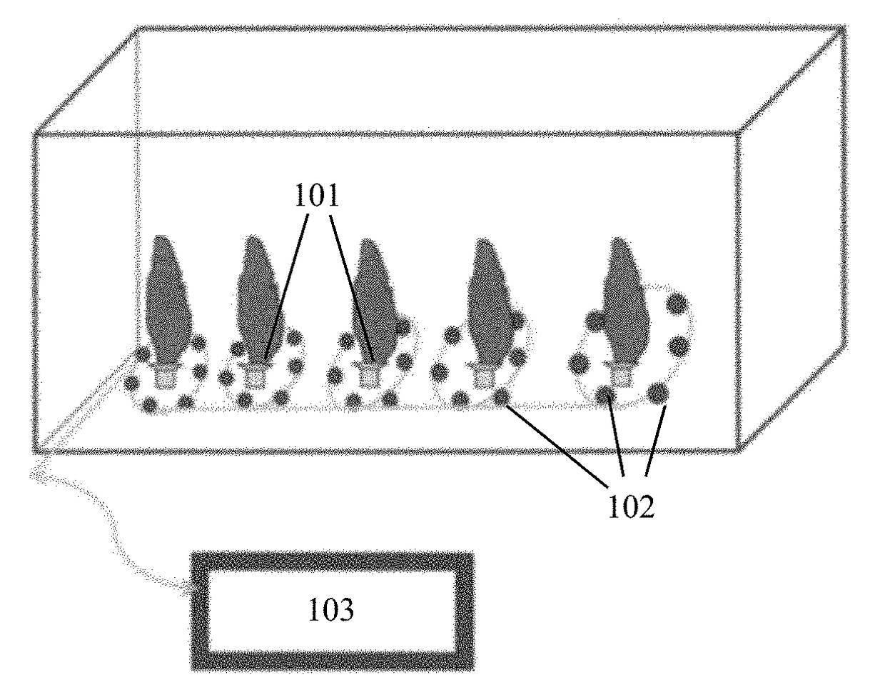
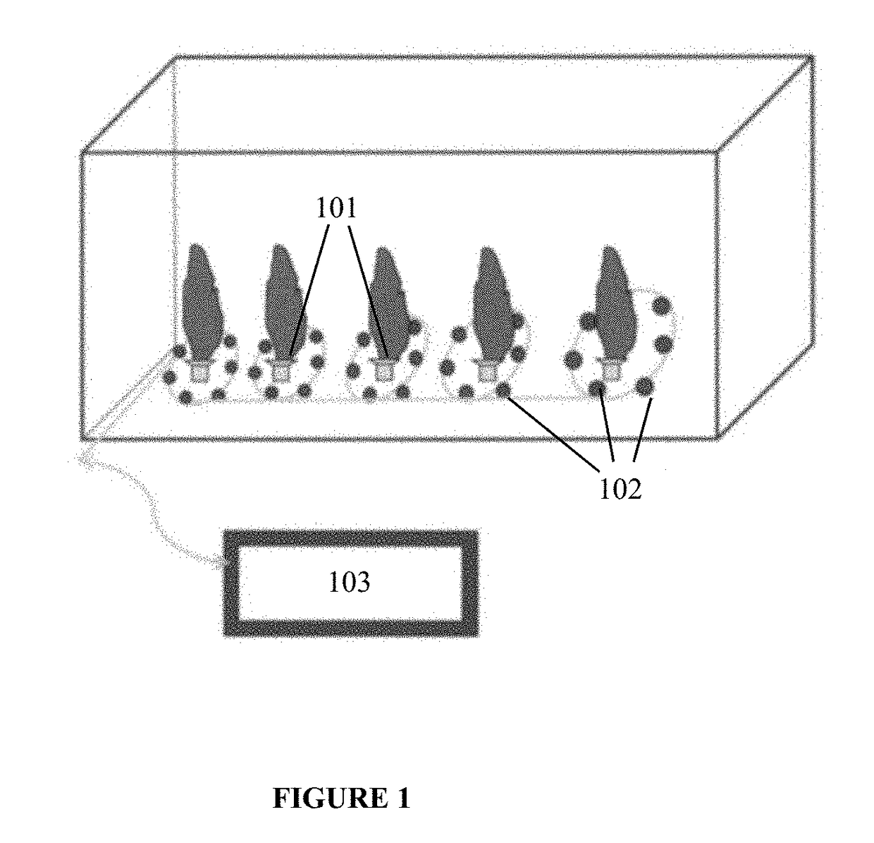
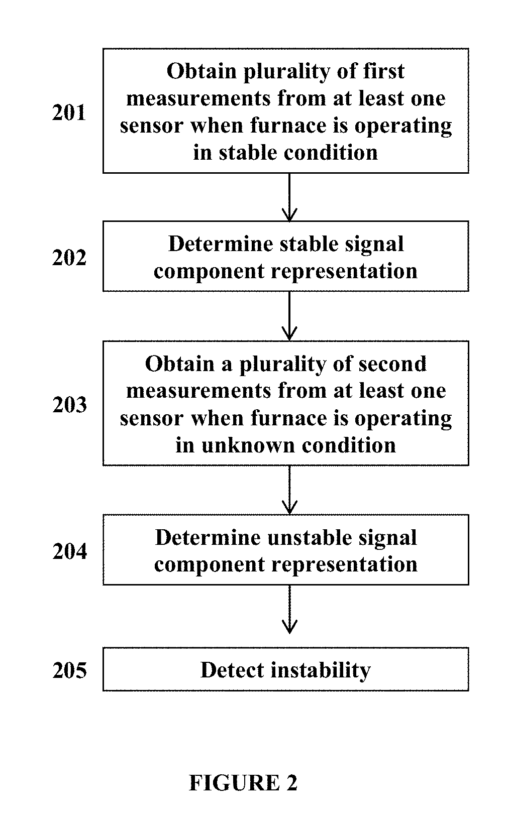
The patent describes a system and method for detecting instability in a furnace with burners. The system includes an acoustic sensor that measures the sound waves generated by the burners when the furnace is operating in a stable condition. These measurements are used to create a stable signal component representation of the furnace. When the furnace is operating in an unknown state, new measurements are obtained and compared to the stable signal component representation. This allows for the detection of any instability in the furnace. The system can also identify which specific burners are causing the instability and provide recommendations to operators to address the issue. Overall, the system provides a way to monitor and mitigate instability in furnaces with burners.

Problems solved by technology

However, such components can involve harsh conditions, such as high temperature, high pressure, and / or a corrosive environment, making it difficult or costly to obtain reliable measurements.
Industrial furnaces, fired heaters, and boilers are used extensively across multiple refinery and manufacturing processes, such as process heating and steam production, and are generally responsible for a large proportion of fuel consumption.
However, these technologies can be more prone to flame instability than traditional processes.
Visual inspection can readily identify flame blowoff, but is generally inadequate for identifying instability prior to blowoff.
Analyzer-based monitoring typically has long latency and lacks the dynamic coverage needed for reliable detection.
Photodetector devices such as flame eye are mainly burner based and expensive for wide-deployment.
Furthermore, the practical use of line-of-sight techniques, such as Tunable Diode Laser-based monitoring, can be restricted due to their design.
New flame monitoring strategies have been introduced, but are limited in various ways.
In addition, draft pressure fluctuation approaches have been reported in the past, but these techniques have been limited to a specific frequency range.

Method used


Image

  • Methods and systems for monitoring burner flame conditions in a furnace
  • Methods and systems for monitoring burner flame conditions in a furnace
  • Methods and systems for monitoring burner flame conditions in a furnace

Examples


embodiment 1

[0093] a method for detecting an instability in a furnace, comprising: obtaining from at least one sensor a plurality of first measurements related to the plurality of burners when the furnace is operating in a stable condition; determining, based at least in part on the plurality of first measurements from the at least one sensor, a stable signal component representation for the furnace; obtaining from the at least one sensor a plurality of second measurements related to the plurality of burners when the furnace is operating in an unknown state; determining, based at least in part on the plurality of second measurements and the stable signal component representation, an unstable signal component representation for the furnace; and detecting, using at least one processor, an instability in the furnace based at least in part on the unstable signal component representation and an instability threshold.

[0094]Embodiment 2: the method of embodiment 1, wherein the sensor is an optical fib...

embodiment 8

[0100] the method of embodiment 1, wherein the unstable signal component comprises a sound waveform.

[0101]Embodiment 9: the method of embodiment 1, wherein the unstable signal component comprises a frequency spectrum.

[0102]Embodiment 10: the method of embodiment 1, wherein the unstable signal component comprises an instability component covariance.

[0103]Embodiment 11: the method of embodiment 10, wherein the instability component covariance is calculated based on a stable covariance matrix and a current covariance matrix.

[0104]Embodiment 12: the method of embodiment 1, wherein the instability threshold corresponds to a deviation from a stable combustion frequency.

embodiment 13

[0105] a method for identifying, in a furnace having a plurality of burners, an unstable subset of burners from among the plurality of burners, comprising: obtaining a plurality of measurements from at least one acoustic sensor; detecting an instability associated with the furnace; computing, using at least one processor, an unstable signal matrix associated with the instability based on the at plurality of measurements; and identifying the unstable subset of burners based at least in part on the unstable signal matrix.

[0106]Embodiment 14: the method of embodiment 13, wherein the method of detecting an instability associated with the furnace comprises any of embodiments 1 through 12.

[0107]Embodiment 15: the method of embodiment 13, wherein the acoustic sensor is an optical fiber acoustic sensor.

[0108]Embodiment 16: the method of embodiment 13, further comprising using eigenvalue decomposition of the unstable signal component representation to obtain at least one dominant eigenvector...


PUM


Abstract

Systems and methods for using at least one sensor for monitoring a condition in a furnace are disclosed. The at least one sensor can be an optical fiber acoustic sensor. The at least one sensor can be coupled to at least one processor that can be configured to receive at least one measurement from the sensor, convert the at least one measurement into a digital format, and determine a condition associated with at least one burner based at least in part on the digital format. The digital format can be, for example, a sound waveform or a frequency spectrum.

Description

CROSS-REFERENCE TO RELATED APPLICATIONS[0001]This application claims priority to U.S. Provisional Application Ser. No. 62 / 280,328 filed Jan. 19, 2016, which is herein incorporated by reference in its entirety.BACKGROUND[0002]Field of the Invention[0003]The presently disclosed subject matter relates to methods and systems for monitoring burner flame performance. More particularly, the presently disclosed subject matter relates to detecting one or more unstable burners within a furnace having multiple burners.[0004]Description of the Related Art[0005]Components of certain equipment, such as that used in the petroleum and petrochemical industry, which includes the exploration, production, refining, manufacture, supply, transport, formulation or blending of petroleum, petrochemicals, or the direct compounds thereof, are often monitored to maintain reliable and optimal operation. However, such components can involve harsh conditions, such as high temperature, high pressure, and / or a corr...

Claims


Application Information

Patent Timeline
Patent Type & Authority Applications(United States)
IPC IPC(8): F23N5/16F23N5/24G01H9/00
CPCF23N5/16G01H9/004F23N2023/00F23N2005/165F23N2023/08F23N5/242F23N2229/00F23N2223/00F23N2223/08
Inventor SONG, LIMINZHANG, YIBING
Owner EXXON RES & ENG CO
Learn More