

LED filament
a technology of led filament and filament, which is applied in the direction of elongating light sources, semiconductor devices of light sources, lighting and heating apparatus, etc., can solve the problems of many homeowners not being able to put in compact fluorescent bulbs, and achieve the effects of long service life, extended lifespan, and remarkable energy efficiency
- Summary
- Abstract
- Description
- Claims
- Application Information
AI Technical Summary
Benefits of technology
Problems solved by technology
Method used
Image

Examples
second embodiment
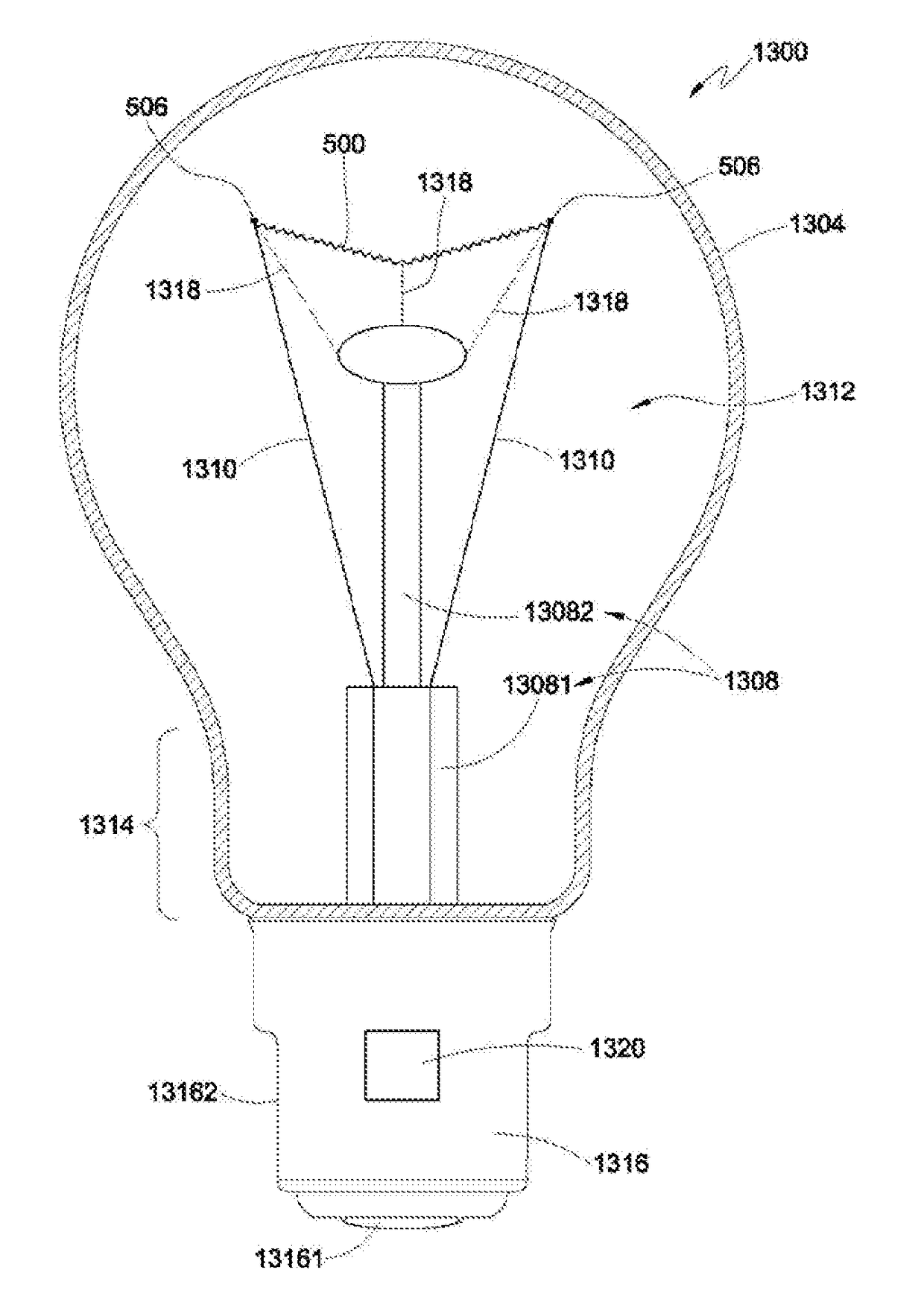
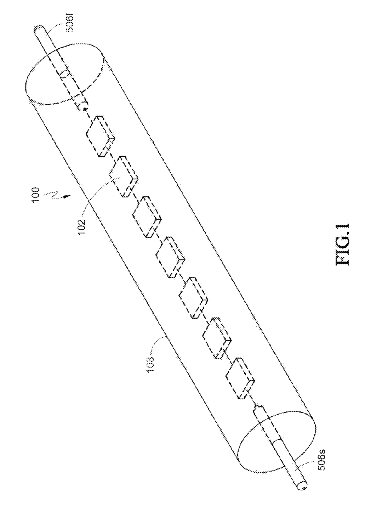
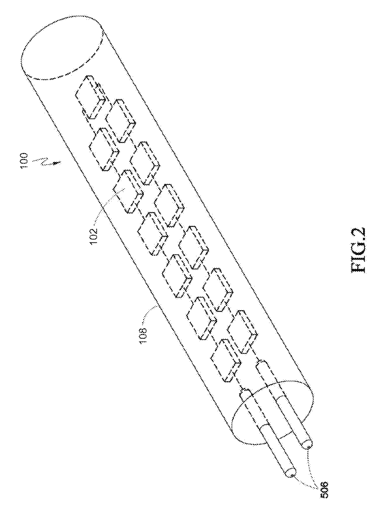
[0258]Please refer to FIGS. 36 to 37. FIG. 36 illustrates a perspective view of an LED light bulb with partial sectional view according to the LED filament and FIG. 37 illustrates a partial cross-sectional view at section 37-37 of FIG. 36.
[0259]According to the second embodiment of the LED filament 100, the LED filament 100 comprises a plurality of LED chips 102, 104, at least two conductive electrodes 506, and a light conversion coating 420. The conductive electrodes 506 are disposed corresponding to the plurality of LED chips 102, 104. The plurality of LED chips 102, 104 and the conductive electrodes 506 are electrically connected therebetween. The light conversion coating 420 coats on at least two sides of the LED chips 102, 104 and the conductive electrodes 506. The light conversion coating 420 exposes a portion of two of the conductive electrodes 506. The light conversion coating 420 comprises an adhesive 422, a plurality of inorganic oxide nanoparticles 426 and a plurality of ...
first embodiment
[0270]Please refer to FIGS. 41A to 41E which illustrate a manufacturing method of an LED filament according to a The manufacturing method of the LED filament 100 shown in FIG. 36 comprises:
[0271]S20: dispose LED chips 102, 104 and at least two conductive electrodes 506 on a carrier 980, referring to FIG. 41A;
[0272]S22: electrically connect the LED chips 102, 104 with the conductive electrodes 506, referring to FIG. 41B; and
[0273]S24: dispose a light conversion coating 420 on the LED chips 102, 104 and the conductive electrodes 506. The light conversion coating 420 coats on at least two sides of the LED chips 102, 104 and the conductive electrodes 506. The light conversion coating 420 exposes a portion of at least two of the conductive electrodes 506. The light conversion coating 420 comprises adhesive 422 and a plurality of phosphors 424, referring to FIG. 41C to 41E.
[0274]In S20, the plurality of LED chips 102, 104 are disposed in a rectangular array. Each column of the LED chips ...
third embodiment
[0301]Next, please refer to FIGS. 43A to 43E which illustrate a manufacturing method of an LED filament according to a The manufacturing method for an Led filament 100 comprises:
[0302]S202: dispose conductive foil 530 on a light conversion sub-layer (base layer 420b), referring to FIG. 43A;
[0303]S204: dispose a plurality of LED chips 102, 104 and a plurality of conductive electrodes 506 on the conductive foil 530, referring to FIG. 43B;
[0304]S22: electrically connect the LED chips 102, 104 with the conductive electrodes 506, referring to FIG. 43C; and
[0305]S24: coat a light conversion sub-layer (top layer 420a) on the surfaces of the LED chips 102, 104 and the conductive electrode 506 where may be not in contact with the conductive foil 530. The light conversion coating 420 (including the base layer 420b and the top layer 420a) coats on at least two sides of the LED chips 102, 104 and the conductive electrodes 506. The light conversion coating 420 exposes a portion of at least two ...
PUM
| Property | Measurement | Unit |
|---|---|---|
| Length | aaaaa | aaaaa |
| Length | aaaaa | aaaaa |
| Fraction | aaaaa | aaaaa |
Abstract
Description
Claims
Application Information